# What Should Buyers Confirm Before Using Bifacial Modules on a Solar Carport?
Buyers should confirm that a solar carport can expose the rear side of bifacial modules to useful, reasonably predictable light; that the canopy, electrical equipment, and monitoring plan are designed for the selected modules; and that the evidence package matches the project jurisdiction and utility process. A bifacial module is not automatically the better procurement choice simply because it can produce from both sides. Its value depends on the actual carport geometry, rear-side shading, surface reflectance, electrical limits, approved mounting arrangement, and the quality of the execution records.
For a bifacial solar carport design, treat the module as one component of an integrated canopy-and-power-system decision. First model the site and vehicle environment. Then translate that model into an auditable module, structure, balance-of-system, and logistics specification. International guidance notes that bifacial system performance is strongly affected by ground reflectivity, array height, row spacing, module spacing, diffuse light, and rear-side non-uniformity; it also notes that bifacial arrays can operate at higher DC currents than comparable monofacial arrays [1]. Those are design inputs to verify, not universal performance promises.
Buyer context and scope boundary
This guide is for commercial property owners, developers, EPC procurement teams, architects, facilities managers, and institutional buyers evaluating bifacial modules above parking. It supports technology selection and sourcing before purchase release; it does not replace a site survey, engineering, permitting review, utility study, or installation instructions.
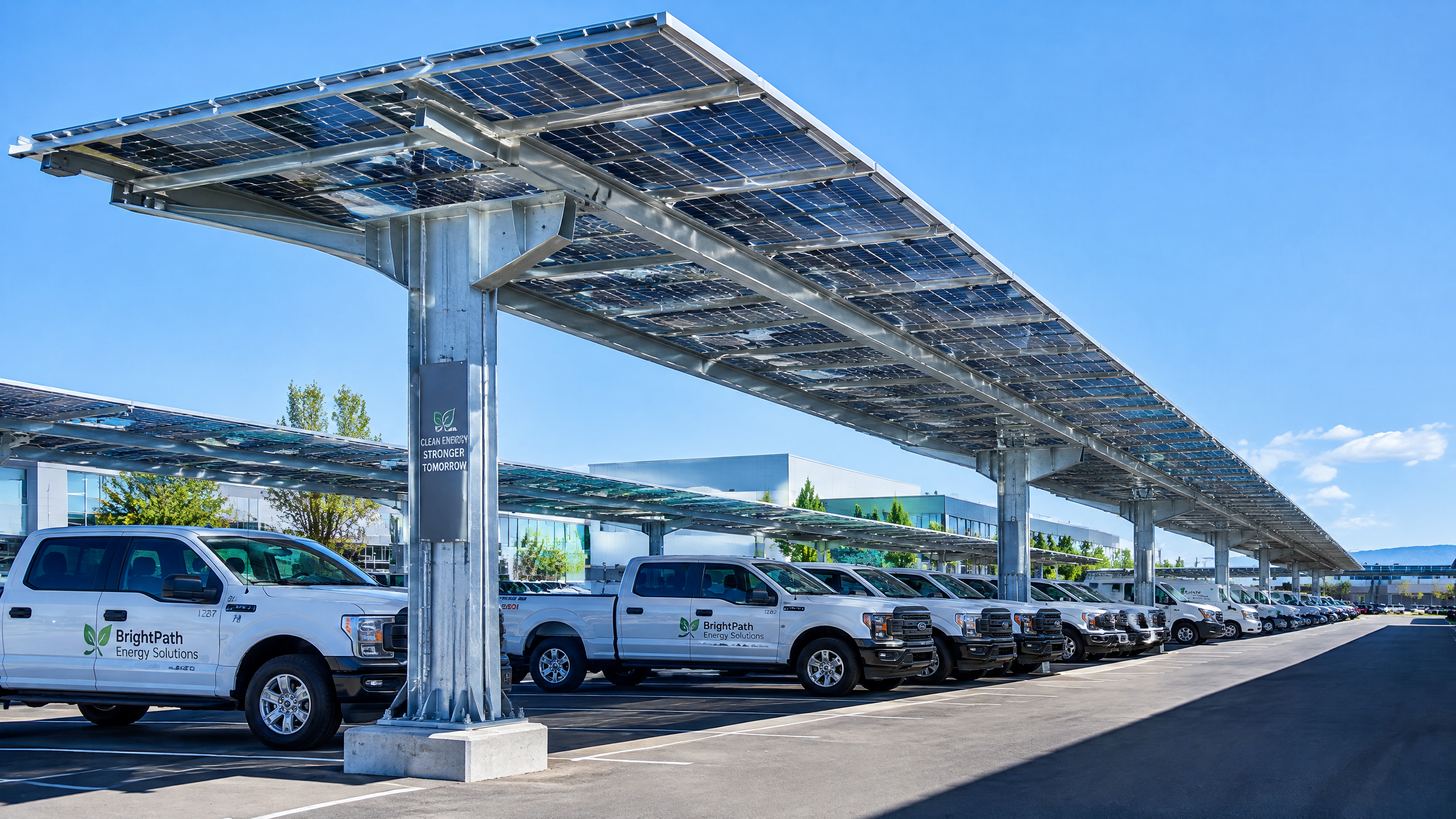
A carport combines an exposed PV environment with vehicle circulation, pedestrian routes, drainage, columns, lighting, utilities, foundations, and an occupied underside. These interfaces can alter rear illumination or dominate the module decision. Bright paving may not help if beams, columns, vehicles, or equipment obscure the rear side. Only a site-specific assessment can establish the usable condition.
The phrase bifacial gain needs care. IEA PVPS defines it as additional energy relative to a monofacial system of the same orientation and size, but front and rear irradiance vary and mismatch and system losses can change the result [1]. Do not specify a fixed uplift without a clear comparison case, model inputs, and operating limits.
Standards and listings are evidence, not project engineering. IEC 61215-1 covers terrestrial-module design qualification and includes bifacial guidance, while cautioning that results do not quantitatively predict module lifetime [2]. IEC 61730-1 addresses safe electrical and mechanical construction but cannot encompass every national or regional code [3]. Local qualified engineers, installers, utility providers, and authorities having jurisdiction (AHJs) determine final decisions.
1. Confirm that the site can provide useful rear-side irradiance
Map the rear-side view before selecting a module
The first question is not “What bifaciality factor is advertised?” but “What will the rear side see here?” Request plans and sections showing module elevation and tilt, bay width and spacing, columns, braces, gutters, trays, lights, signs, nearby buildings, vegetation assumptions, and typical vehicles. Do not rely on a single rendering.
Rear illumination comes from diffuse sky light, reflections, and direct paths. IEA PVPS identifies albedo, array height, spacing, and diffuse fraction as factors that can increase bifacial gain [1]. Translate these into inspectable conditions: surface finish, dirt or water patterns, underside openness, and rear-side shade. A “high-reflectance” label is not enough without its expected condition, maintenance responsibility, and model representation.
Separate fixed geometry from variable parking conditions
Carports introduce changing obstructions: vehicles, trucks, bicycles, snow piles, temporary storage, people, and signs. Define whether the estimate assumes empty bays, normal occupancy, or a conservative scenario. The aim is not a perfect vehicle model; it is to avoid comparing an empty-under-canopy proposal with normal operations.
Also review non-uniformity. IEA PVPS explains that rear irradiance is less uniform than front irradiance and racking creates inhomogeneity that can affect module and string mismatch [1]. A rear-light map should show repeated shadows from purlins, clamps, columns, trays, or nearby objects—not only an average value.
| Site condition to confirm | Procurement question | Evidence to request | Why it matters |
|---|---|---|---|
| Surface below modules | What material, colour, texture, drainage state, and maintenance condition are assumed? | Finish schedule, photos of comparable existing areas, model input log | Reflected light is a major rear-side input; surface conditions can change over time. |
| Underside openness | Which beams, purlins, braces, trays, and luminaires obstruct the rear view? | Canopy section, coordination model, obstruction/shading study | Structural and MEP items may reduce or unevenly distribute rear irradiance. |
| Parking and operations | Are parked vehicles and temporary uses included in the model assumptions? | Operations assumptions and sensitivity note | Carport occupancy can differ materially from an empty-bay visualization. |
| Nearby and future shade | Which trees, buildings, signs, or expansion zones were evaluated? | Shade scene list, site photos, development plan review | A useful rear-side condition should remain credible after normal site changes. |
| Cleaning and drainage | How will dust, debris, water marks, and drainage be managed? | O&M concept and drainage drawings | Soiling and water can change optical conditions and access. |
Require a baseline and sensitivity cases, not one unqualified output. The modeller should state weather data, geometry, orientation, rear-side method, surface and shade assumptions, DC/AC configuration, export constraints, and losses. This permits a common-basis comparison and traceable changes.
2. Turn bifacial module specifications into comparable purchase evidence
Ask for data that describes both faces and the tested configuration
A data sheet is the beginning, not the end. Request the exact product identifier; revision-controlled data sheet; construction identifier where available; electrical ratings; dimensions and mass; mounting zones; clamp or rail requirements; connector data; electrical limits; and installation manual. Record front and rear electrical information with its irradiance conditions. Do not compare a rear-illuminated headline figure with a front-only rating without a defined basis.
Bifacial I–V measurement has additional requirements because both faces contribute. IEC TS 60904-1-2 describes I–V procedures for single-junction bifacial devices, including modules [4]. Ask how stated electrical values, bifaciality, and tolerances were determined and which documents identify the test basis.
IEC 61215-1 addresses terrestrial-module design qualification and bifacial testing guidance [2]; IEC 61730-1 addresses construction relating to electrical shock, fire, injury, and environmental stress [3]. Applicable editions and required markings depend on the market. Request the evidence expected by the project’s AHJ and insurer, not a generic “certified” statement.
Compare a complete installed-system case, not just watts on a label
Create a controlled comparison sheet with orientation, usable canopy area, layout, module count, stringing, inverter constraints, weather inputs, and output limits. A larger module can change handling, clamps, rail spans, layout density, and string count; rear-side response can change current calculations. These interactions can matter more than a single label value.
| Evidence item | What to verify before award | Buyer action if unclear |
|---|---|---|
| Product identity | The offer, data sheet, certificates, packing list, labels, and installation manual name the same module family and revision. | Put the exact model and approved substitution process in the contract documents. |
| Front and rear data | Rating conditions, bifaciality information, electrical limits, and stated tolerances are traceable to product documentation. | Ask for a manufacturer clarification and align the energy model inputs. |
| Qualification and safety evidence | Evidence is applicable to the module construction and the project jurisdiction; expiry and scope are checked. | Have the local designer and AHJ-facing team confirm acceptance needs. |
| Mechanical interface | Approved mounting zones, clamp instructions, rail contact, fastener requirements, and torque instructions are available. | Do not assume a familiar rail arrangement is approved for the new module. |
| Environmental fit | The proposed product documentation addresses the site’s relevant exposure categories and cleaning constraints. | Ask qualified local engineers to review site-specific environmental conditions. |
| Traceability | Lot, serial, shipment, and document-control method are defined before dispatch. | Make traceability records a required turnover deliverable. |
Do not infer field behaviour from a data-sheet category alone. IEC cautions that qualification results are not a quantitative lifetime prediction [2]. Use product evidence alongside quality documentation, engineering review, and site acceptance controls.
3. Verify the canopy structure, module interface, and occupied-space constraints together
Make the structural engineer’s load path and the module manual meet
A solar carport is a structural assembly as well as a PV platform. The engineer of record determines the structural system, foundations, wind, snow, seismic, rain, thermal movement, drainage, and local actions. The buyer should ensure inputs use the selected module, rail, clamp, cable-management, and accessory configuration—not a provisional product.
Give the structural team the installation manual and mounting-zone diagram early. Confirm orientation, rail direction, support count, clamp offsets, edge distances, fasteners, frame contact, and glass-glass restrictions. A product change requires a revised compatibility review. Do not resolve an interface mismatch by moving clamps or drilling without documented engineering and manufacturer approval.
The underside affects safety and PV output. Coordinate cable routes, junction boxes, bonding, lights, cameras, signs, fire equipment, and drainage for structural, maintenance, and rear-shading effects. Address vehicle impact, clearances, and accessible routes through local architectural, civil, and code review.
Confirm mounting-system scope and bonding compatibility
Where it applies, UL describes UL 2703 as covering PV mounting systems, clamps, and ground lugs; it emphasizes proper bonding and code-compliant grounding [5]. This is not universal approval of a carport. Request mounting evidence, module compatibility documentation, bonding details, and jurisdictional scope.
Ask whether the module-and-rack combination is identified in the applicable documentation and whether rails, clamps, bonding hardware, frames, and fasteners match the configuration. Keep structural calculations distinct from product listing evidence.
4. Recalculate the DC design, inverter operating range, and utility interface
Bifacial modules can alter the electrical envelope. IEA PVPS notes that higher current can require changes to wire, fuse, and inverter sizing, and that ohmic losses and inverter clipping can reduce system-level results [1]. Ask the electrical designer to use the selected module’s data, rear-irradiance assumptions, temperature conditions, codes, and equipment ratings.
Review maximum string voltage, current and protection, ampacity and voltage drop, connector compatibility, combiner and disconnect ratings, inverter range, transformer and switchgear limits, grounding, monitoring, and export control. Update the review when module count, topology, or DC/AC ratio changes.
Distinguish annual energy modelling from instantaneous equipment limits. State the design cases for both. If export is limited, document how controls, inverter settings, and metering will be coordinated rather than assuming all additional module output can be exported.
Utilities control interconnection. EPA explains that standards define how PV connects to the grid and advises checking the local provider’s process and timeline [6]. Engage early so system size, inverter, protection, transformer, metering, communications, or export controls do not emerge after procurement. Follow equivalent local processes outside the United States.
5. Define measurement, commissioning, and safety coordination before procurement
Make performance claims measurable and bounded
Monitoring should help separate normal variation from a design or installation issue. Define required DC, AC, irradiance, temperature, weather, meter, and availability data; sensor locations; maintenance; time stamps; gaps; and calibration records. Because rear irradiance can be non-uniform, one rear sensor may not represent every module. The qualified designer should select the arrangement.
Define commissioning evidence in advance: serial-number capture, polarity and continuity checks, applicable insulation and grounding checks, string records, inverter settings, communications verification, shutdown demonstration, as-builts, and manuals. State acceptance criteria and test conditions. Do not accept an output claim based only on one sunny-day snapshot.
Coordinate with fire, operations, and maintenance stakeholders
PV systems add electrical hazards. DOE notes that qualified installations must follow current safety codes and responders need to identify and shut down PV while recognizing hazards [7]. Coordinate early with fire and building authorities, facilities, and the installer on access, markings, disconnects, emergency information, and related site systems. Requirements are local.
Design maintenance access before turnover. Confirm safe access to modules, drains, gutters, lighting, cables, inverters, and monitoring; cleaning decisions; and controls over mounting or wiring changes. Handover should use the final single-line, as-builts, shutdown information, inspection records, and asset register.
Mid-article CTA: Need a structured document list for a bifacial carport RFQ? Share the site brief with info@carportiva.com or submit it through /inquiry for sourcing coordination.
6. Require factory, shipment, and installation evidence that preserves traceability
A suitable module becomes difficult if evidence is lost between factory release and commissioning. Use a document register with owner, due date, revision, and reviewer; connect the module and mounting interface to shipment and installed-asset records.
Before shipment, request agreed product data, applicable evidence, manuals, packing configuration, serial or lot traceability, any contractually required conformance certificate, and agreed inspection records. A generic factory record does not prove every module is undamaged or project-suitable; it is one part of the evidence chain.
For shipment, confirm packaging orientation, lifting, unloading, storage, impact and moisture protection, truck access, delivery windows, laydown space, and visible-damage records. Sequence foundations, steel, drainage, rails, modules, electrical work, trenching, and energization to avoid repeated handling.
At receipt, check quantity, labels, packaging, visible damage, documents, and exceptions before distribution. Capture photos and traceability data. Use installation hold points for fasteners, clamps, bonding, cable management, connectors, labels, and as-builts. Qualified installers and engineers determine local inspection and sign-off requirements.
| Project stage | Evidence or coordination item | Buyer confirmation |
|---|---|---|
| Pre-award | Model-specific data, mounting interface, scope matrix, utility assumptions, document register | The bid is based on an identifiable product and a common design basis. |
| Factory release | Product identity, agreed quality records, packing method, lot/serial traceability, shipping instructions | Records can be tied to the purchase order and later asset register. |
| Transit and receipt | Delivery plan, unloading method, laydown controls, damage and discrepancy log | Material is inspected before installation and exceptions are visible. |
| Installation | Approved drawings, method statements, inspections, torque/connection records where specified, change log | Field work follows controlled documents; deviations are reviewed. |
| Commissioning and handover | Test records, settings, as-builts, monitoring setup, safety information, O&M files | The owner receives a usable, traceable operating record. |
Numbered buyer workflow: a bifacial solar carport design checklist
- Set the decision boundary. Define the parking area, operational hours, vehicle types, future development, desired energy use, export assumptions, schedule constraints, and procurement roles. State whether bifacial modules are being compared with monofacial alternatives or specified outright.
- Commission a coordinated site survey. Capture canopy location, grades, drainage, surface finishes, utilities, trees, buildings, traffic routes, pedestrian routes, accessible areas, signage, lighting, and likely future obstructions. Record photographs from both the proposed front and rear module perspectives.
- Request a bifacial-specific layout study. Require an annotated plan, sections, rear-side shading or irradiance assessment, and documented modelling assumptions. Include conservative or alternative scenarios for surface condition and normal parking use.
- Create a controlled module comparison sheet. List exact model identifiers, electrical data, dimensions, mass, mounting requirements, relevant evidence, anticipated stringing, and differences in canopy layout. Keep all bidders on the same comparison convention.
- Run structural and interface review. Provide final candidate-module documents to the engineer of record. Confirm foundations, steel, rails, clamps, drainage, cable routes, vehicle-impact protection, clearances, and maintenance access as one coordinated package.
- Run electrical and interconnection review. Recalculate DC and AC equipment using the bifacial design assumptions. Engage the utility early and document the current interconnection path, meter requirements, controls, and unresolved study items.
- Confirm local compliance pathways. Have local qualified professionals identify applicable building, electrical, fire, accessibility, zoning, and utility requirements. Confirm what documentation the AHJ and other stakeholders expect; do not substitute international standards for local approval.
- Lock the quality and logistics plan. Establish document submittals, approved substitutions, traceability, packing, delivery, storage, receipt inspection, installation hold points, nonconformance handling, and change control before goods ship.
- Commission against defined evidence. Verify configuration, wiring, protection, monitoring, safety information, and final records under the approved commissioning plan. Reconcile installed module identities with the asset register.
- Handover an operating baseline. Deliver as-builts, manuals, maintenance-access plan, monitoring ownership, emergency information, inspection records, and the final list of modelling assumptions so future performance reviews have context.
7. Use a buyer evidence schedule to control procurement interfaces
Before purchase release, issue a controlled buyer evidence schedule with the evidence owner, revision, reviewer, due date, and acceptance status. It should support—not replace—the local engineer, AHJ, utility, and qualified installer. Use it to retain design assumptions and identify changes needing coordinated re-review. The schedule records evidence; it does not approve a configuration.
| Interface | Evidence to schedule | Buyer review point |
|---|---|---|
| Bifacial module | Exact product and document revisions; front and rear electrical data with stated test basis; installation instructions; mounting zones; and applicable qualification and safety evidence. | Confirm the electrical model and module interface use the offered product. IEC TS 60904-1-2 addresses bifacial I–V procedures; IEC 61215-1 and IEC 61730-1 have different qualification and safety purposes [2] [3] [4]. |
| Racking and bonding | Rail, clamp, fastener, bonding, and grounding details; module-compatibility information; structural calculations; and installation instructions. | Have the engineer of record and installer review the final combination. Where applicable, distinguish UL 2703 mounting-system evidence from project-specific structural and code decisions [5]. |
| Ground and underside conditions | Finish and drainage schedules, photographs, maintenance responsibility, parking-use assumptions, and reflected-light and obstruction inputs. | Check expected operating conditions, not only a new-surface rendering. IEA PVPS identifies albedo, geometry, and rear-side non-uniformity as relevant factors [1]. |
| Canopy geometry | Coordinated plans and sections showing module elevation, tilt, spacing, supports, purlins, columns, cable routes, lights, signs, and repeat rear-side shading. | Update layout and electrical review if a module, member, route, or clearance changes; geometry can affect rear illumination and mismatch [1]. |
| Commissioning interfaces | Approved single-line, settings and export-control records, utility requirements, monitoring configuration, test plan, serial capture, inspection records, and final as-builts. | Allocate test and turnover items before energization. Interconnection processes are utility-specific, and safety coordination remains subject to local requirements [6] [7]. |
For each change, record the affected model input, drawing, calculation, product document, and approval path before site release. A completed schedule is not a warranty of annual yield, lifetime, code approval, or utility acceptance. At commissioning, reconcile equipment identities and settings with the schedule to create an auditable operating baseline.
Frequently asked questions
Is a bifacial module always better for a solar carport?
No. A bifacial module can be a suitable option when its rear side has a useful view of sky and reflective surroundings, but its result is site- and layout-dependent. IEA PVPS identifies albedo, spacing, height, diffuse conditions, and rear-side non-uniformity as important variables [1]. Compare a documented bifacial case with a documented alternative rather than assuming an uplift.
Can a buyer use the module’s bifaciality figure as the project energy increase?
No. Bifaciality describes a module characteristic under stated conditions; it is not an annual carport output forecast. System output also depends on the actual rear irradiance distribution, shadows, mismatch, wiring losses, inverter clipping, operating limits, and weather. Ask the modeller to identify how module information becomes system assumptions and results.
Does a bright pavement guarantee useful rear-side performance?
No. Surface reflectance is only one input. Its actual condition can be affected by soiling, water, wear, vehicle use, drainage, and shadow. The rear surface may also be obstructed by canopy members or parked vehicles. Require the specified finish and its expected operational condition to be shown in the study.
Can the same racking and electrical design used for monofacial modules be reused?
Not automatically. The selected module can change mounting zones, clamp requirements, dimensions, mass, and electrical current assumptions. The IEA report notes the need to consider higher bifacial current in wire, fuse, and inverter sizing [1]. Have the engineer and installer verify the final equipment combination and applicable mounting evidence.
Are IEC module standards enough to obtain project approval?
No. IEC 61215-1 addresses PV module design qualification and IEC 61730-1 addresses construction safety requirements, but IEC 61730-1 explicitly says it cannot encompass all national or regional codes [2] [3]. Building, electrical, fire, utility, planning, and accessibility requirements are determined locally. Local qualified engineers, installers, utility providers, and AHJs make the final project decisions.
What should be recorded at delivery and installation?
Record the delivered model identity, quantities, packaging condition, visible damage, exceptions, serial or lot information under the agreed traceability method, approved drawings, installation inspections, approved field changes, electrical configuration, commissioning data, and as-built records. These records create a chain from the sourcing decision to the installed asset.
Conclusion
The right question is not whether bifacial modules are technically capable of generating from both sides. It is whether the proposed bifacial solar carport design gives the rear side a credible, documented operating environment and whether every connected decision has been checked. Buyers should confirm rear-side light conditions, module test and product data, canopy and mounting compatibility, electrical design margins, utility coordination, safety planning, and traceable delivery-to-handover records before committing equipment.
Use the standards and technical sources below to frame the evidence request, then have local qualified engineers, installers, utility providers, and authorities determine final project decisions. For a procurement brief or document checklist, contact info@carportiva.com or use /inquiry.
References
Bring the actual project brief to the engineering table.
Share your location, layout, target application and available technical inputs. Carportiva can help identify the relevant product-interface information before a project-specific commercial discussion.
Request a project discussion