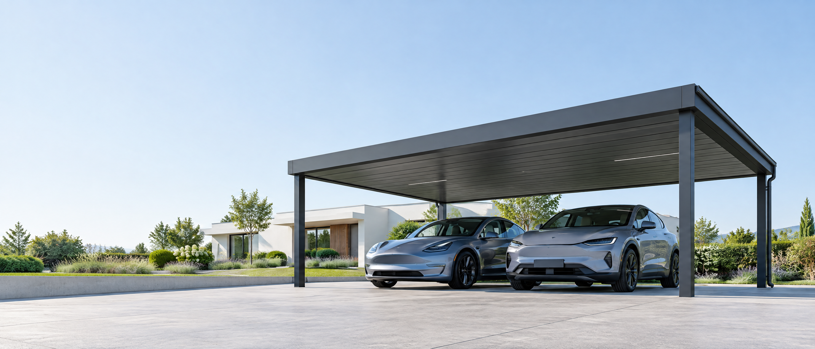
# How Do You Integrate Lighting Into a Commercial Carport Without Creating Rework?
Direct buyer-facing answer (within 140 words): Successful carport lighting integration depends on early, single-source electrical coordination: specify photometrics, circuit loads and conduit routes during design development; allocate photometric responsibility to the lighting designer and electrical responsibility to the electrical engineer/contractor; lock mounting details to the structural supplier and confirm attachment points with the carport manufacturer before steel fabrication. This guide covers engineering-focused decisions for commercial carports (covered parking for workplaces, retail, and multi-tenant developments), including lighting purpose, photometric-design responsibility, electrical loads/routes, mounting, glare/visual comfort, maintenance access, emergency/security interfaces, controls and commissioning scope boundaries.
Buyer context and scope boundary
- Audience: procurement managers, electrical engineers, MEP coordinators and carport project managers specifying or buying commercial carport systems in Europe and North America.
- Scope: This guide focuses on electrical coordination and specification for standalone and canopy-mounted carports (including integrated PV canopy systems such as /products/solargrid). It does not replace local codes, structural calculations, or project-specific civil foundation design; seek structural review and site investigations separately (/guides/carport-foundation-requirements). It assumes coordination with the carport manufacturer for connection details and does not prescribe universal mounting spacings, lighting levels or footing sizes.
Core principle
Minimise rework by allocating responsibilities, fixing interfaces, and documenting routes early. Use a single, version-controlled coordination drawing set that shows conduit routes, mounting zones, lighting control zones, and maintenance access. When the lighting design, electrical design and carport supplier share clear boundaries, fabrication conflicts and on-site change orders fall dramatically.
Decision 1 — Define lighting purpose and performance before fastening anything to steel
- H3: Clarify mission profile and operating modes
- Define who the lighting serves (pedestrians, drivers, security cameras, EV chargers) and the expected operating schedule (dusk-to-dawn, occupancy-based, scheduled dimming). Security CCTV and license-plate capture require different aiming and glare constraints than general area lighting; include these requirements in the project brief.
- Document emergency use: if the carport is part of egress routes or emergency vehicle access, note required interfacing with building emergency power or local fire/life-safety systems; this determines circuit segregation and transfer equipment selection.
- H3: Photometric design responsibility and deliverables
- Assign photometric responsibility to the lighting designer (or the electrical engineer if performing lighting design). Deliverables must include: IES/IESNA files or equivalent, predicted illuminance/luminance plots over the parking aisles, specified maintenance factor assumptions, fixture aiming and tilt, and a luminaire schedule with mounting heights and weights. Require that photometric files reference the actual carport geometry supplied by the structural vendor to avoid mismatch.
- Require the lighting designer to provide “no-go” zones for fixtures and conduit where PV modules, structural bracing or service walkways exist.
Decision 2 — Electrical loads, routing and cabinet placement
- H3: Circuits, load categorisation and segregation
- Early load budgeting prevents undersized feeders and rework. Categorise loads: general lighting, security/standby lighting, emergency egress lighting, controls, AV/CCTV and EV charging (if present). Each category may require separate metering, emergency power, or dedicated ground-fault protection.
- Specify where emergency lighting is fed from (normal vs. emergency generator or UPS). If emergency lighting is required, document transfer switch location and sketch upstream protection coordination.
- H3: Conduit routes, raceways and pull-clearances
- Lock conduit corridors that can be embedded into carport beams or run through columns. On the coordination drawing, show primary feeder routes, risers to inverter or distribution boards, and final run to each luminaire. Identify required pull boxes and clearance requirements per local electrical practice; require the electrical contractor to confirm a maximum run length between pull points for the chosen cable type.
- Provide conflict-avoidance zones for PV wiring if the design uses /products/solargrid; isolate PV DC trays from AC lighting conduits to reduce interference and simplify maintenance. Reference UL or local guidance if equipment is UL-listed.
- H3: Distribution and control cabinet placement
- Place electrical distribution and control cabinets where they are accessible, weather-protected and coordinated with civil access. Cabinets often mount to a nearby building wall or a dedicated pad-mounted enclosure; cabinet placement affects feeder lengths and overcurrent devices. Require cabinet mounting detail reviews with the carport supplier to avoid clashes with structural attachments.
Decision 3 — Mounting, structural attachments and weatherproofing
- H3: Who designs the attachment and who verifies the capacity
- The carport manufacturer (supplier of /products/nordarch, /products/nordflat, /products/titan) supplies the structural steel geometry and permissible attachment zones; the electrical or lighting engineer provides the luminaire point loads and eccentricity data. Responsibility boundary: the supplier verifies attachment feasibility given the structural members, while the project structural engineer verifies that the carport foundations and members can accept the additional loads and moments. Use the Aluminum Design Manual or steel design standards as applicable [12] [11].
- Require the supplier to provide certified connection details for shop drilling, welds, or clamp interfaces before fabrication. Lock fastener types (anchor rods or clamps) and hole patterns at design freeze.
- H3: Specifying luminaire supports and ingress protection
- Specify whether luminaires mount directly to the underside of the canopy, to dedicated arms, or to columns. Include environmental ingress ratings (IP rating) and corrosion protection expectations referencing local exposure and coatings standards (e.g., hot-dip galvanising specs or ISO 12944 for paints) [13] [14].
- Provide details on vibration isolation if luminaires are mounted to elements subject to wind-induced vibration or PV module frames. Use manufacturer’s torque and fixation instructions in the specification.
- H3: Penetrations, sealing and drainage
- Show roof or canopy penetration details for conduits and junction boxes. Require weather-sealed flashings or factory-fitted gland plates to be supplied by the carport manufacturer or the electrical contractor depending on the chosen responsibility split. Ensure that cable entry points do not impede drainage routes; reference stormwater guidance for impervious-area considerations if canopy cover affects runoff patterns [7].
Decision 4 — Visual comfort and glare management
- H3: Align optics with use-case and camera needs
- Require the lighting designer to provide glare indices (UGR or equivalent) and lighting orientation constraints where CCTV or license-plate capture is required. Position luminaires and select beam spreads to avoid direct view into driver sightlines and cameras. Document permitted uplight limits to comply with local light pollution controls if applicable.
- H3: Color rendering and correlated colour temperature (CCT) boundaries
- Specify a CCT range and minimum CRI for tasks and security camera performance, but avoid absolute universal mandates; tie requirements to camera vendor recommendations where CCTV dependency exists. Indicate dimming and color control needs if tunable lighting is part of the control strategy.
Decision 5 — Maintenance access, replacement strategy and lifecycle
- H3: Accessibility for lamp or driver replacement
- Define who will maintain luminaires (owner, facility management or supplier under O&M contract). If routine replacement requires elevated access equipment, specify fixture height limits and placement to keep replacements from impeding traffic. Consider using pendant or column-mounted fixtures at reachable heights to reduce crane or lift needs.
- H3: Spares, labeling and documentation
- Require as-built photometric files, luminaire serial numbers, spare parts kits and a single-line wiring diagram at handover. Label circuits and junction boxes on-site and in the project document management system.
- H3: O&M responsibility split
- Clarify whether the supplier will provide extended maintenance, firmware updates for networked controls, or whether the owner will hold these responsibilities. If integrated with PV or storage systems (/products/solargrid), specify coordination for shutdown procedures during maintenance per PV best practices [18] [19].
Decision 6 — Controls, cybersecurity and commissioning
- H3: Control architecture and interoperability
- Determine control architecture early: centralised PLC panel, distributed node-based wireless controls, or dedicated fixture-level controls. Controls dictate wiring (e.g., one control pair per run), gateway locations and network cabling routes. For EV charging or smart-grid interactions, coordinate with distributed energy interconnection checklists [20].
- For carports that incorporate PV generation, ensure controls coordinate with inverter protective functions. Require control protocol and API documentation in contract.
- H3: Commissioning scope and acceptance testing
- Define commissioning tests: photometric verification against design plots, dimming functional tests, failover to emergency power, control network latency and cybersecurity baseline checks. Assign responsibility: the lighting designer verifies photometrics; the electrical contractor executes tests and records results; the owner or a third-party commissioning agent signs acceptance.
- Require a defect list and a post-commissioning walkthrough to confirm that mounted equipment matches issued shop drawings.
Tables — Practical comparisons and allocation matrix
- Table 1: Responsibility allocation (example)
| Task | Typical Responsible Party | Deliverable or Output |
|---|---|---|
| Photometric lighting design and IES files | Lighting designer or electrical engineer | IES files, illuminance/luminance plots, aiming notes |
| Structural connection feasibility | Carport manufacturer (supplier) | Attachment zone drawings, allowable loads |
| Structural capacity verification | Project structural engineer | Calculations, foundation checks |
| Conduit routing and final cable pull | Electrical contractor | Coordination drawings, pull box locations |
| Controls integration | Controls supplier / electrical contractor | Control sequence of operations, network diagram |
| Commissioning and photometric verification | Lighting designer & electrical contractor | Test reports, recorded lux readings |
- Table 2: Typical attachment decision factors
| Factor | Attach to Canopy Underside | Attach to Column/Arm |
|---|---|---|
| Ease of luminaire aiming | Limited | Greater aiming flexibility |
| Access for maintenance | May be harder if high | Easier if at column height |
| Conflict with PV panels | Higher risk under panels | Lower risk if offset |
| Structural load transfer | Distributed to roof members | Localised to column connections |
Six-step buyer workflow
- Project brief and mission profile — define users, security needs, camera interplay, operating hours and maintenance model.
- Early interface lock — procure or receive carport geometry from supplier and freeze attachment zones before luminaire selection or steel fabrication. Reference /products/nordarch, /products/nordflat, /products/titan as applicable for geometry.
- Photometric design and conduit routing — lighting designer produces IES files and the electrical engineer produces feeder and conduit routes; coordinate these in a single federated model (BIM/CAD).
- Shop-drawings and attachment sign-off — carport supplier issues attachment detail drawings; electrical contractor signs off on required penetrations and cabinet locations.
- Fabrication and pre-installation checks — supplier confirms hole positions and clamp locations; electrical team confirms pull-box placement and cable lengths before steel dispatch.
- On-site installation, commissioning and handover — perform photometric verification, control functional tests and emergency/standby tests; hand over as-built documentation and spares.
Mid-article CTA If you are preparing a specification package, Carportiva can provide geometry-ready detail packs and review attachments for /products/nordarch, /products/nordflat, /products/titan and /products/solargrid. Start a free inquiry at /inquiry or email info@carportiva.com to request coordination files.
Controls, networking and security details
- Control strategies: occupancy sensors, astronomical scheduling, dim-to-off during daylight and networked adaptive dimming. Specify required response time and central monitoring expectations.
- Cybersecurity: Require hardened network gateways, separate VLANs for building systems, regular firmware update responsibilities and role-based access control to the lighting management platform. Document backup and rollback procedures for updates.
- Interlock with security: If lighting is to increase on alarm triggers (e.g., perimeter breach), define the interface (dry contact, network API) and specify priorities between alarm-triggered lighting and scheduled energy-saving modes.
Emergency and security interface
- Emergency circuits: Draw single-line schematics showing which luminaires are on emergency power and how they are separated physically and electrically. Confirm whether emergency lighting requires battery-backed fixtures or centralised UPS/generator tie-in.
- Security integration: Define camera sightlines, avoid uplight that reduces camera contrast and confirm that lighting controls support preset scenes for forensic evidence capture (pre-event high-intensity mode followed by reduced maintenance output).
Glare, spill and neighbour considerations
- Provide the lighting designer with site context: adjacent dwellings, roadways, and wildlife areas. Ask for predicted spill light contours with skyglow and direct glare limits noted. Where needed, require shields or directional optics to reduce spill; document these as procurement requirements.
Maintenance planning and life-cycle documentation
- Work with the carpark owner and facilities team to schedule access windows for maintenance that minimise operational disruptions. Provide a maintenance manual specifying cleaning frequencies, driver replacement procedures and inspection logs. For PV-integrated carports, follow PV O&M best practice recommendations for coordinated shutdowns during maintenance [18] [19].
Contract clauses and tender language snippets
- Include a clause to require that the supplier provides as-built BIM geometry and attachment zones 30 days before steel fabrication to permit electrical and lighting review.
- Require that the lighting supplier furnish luminaire test reports and that the electrical contractor provide cable and conduit as-built records and megger results at handover.
- Stipulate that any field changes must be logged and priced by change order after an engineered verification by the structural engineer and the carport supplier.
FAQ
- Q: Who signs off final luminaire attachment holes on the carport steel?
A: The carport supplier issues attachment configuration and the buyer’s structural engineer verifies capacity; the electrical contractor must accept the positions prior to fabrication to avoid rework.
- Q: How do I prevent PV wiring and lighting wiring getting tangled on integrated canopies?
A: Require a segregation plan on the routing drawings and specify separate trays or cable channels. Include no-go zones for DC cabling near AC lighting runs and ensure routing is reviewed in a coordinated model.
- Q: Who is responsible for emergency lighting operation?
A: The project should document whether emergency lighting is tied to building emergency power (design team/MEP) or to fixture-level battery back-up (lighting supplier); responsibility for commissioning should be assigned to the electrical contractor with photometric verification by the lighting designer.
- Q: What documentation is essential at handover?
A: As-built photometric files, luminaire schedules with serials, single-line diagrams, control sequences, spares list and maintenance manual. Also require a commissioning report with measured lux values and control functional test records.
- Q: My carport supplier proposed factory-installed gland plates for wiring. Who pays for additional penetrations later discovered?
A: Contractually, field modifications after shop drawing sign-off are typically owner-directed changes; include a clause requiring coordination reviews pre-fabrication to minimise field change orders.
Conclusion
Avoid rework by freezing interfaces early: lock photometric intent, conduit corridors and attachment zones before structural fabrication. Allocate photometric responsibility to the lighting designer, structural connection feasibility to the carport supplier, and structural capacity verification to the project structural engineer. Use coordinated shop drawings and a formal commissioning process to confirm photometric and control objectives on completion. For PV-integrated projects, coordinate DC and AC segregation and follow PV O&M best practices.
Closing CTA Request geometry-ready attachment packs, luminaire load sheets or a coordination review for your next commercial carport project at /inquiry or email info@carportiva.com.
Four-image plan (five-column table)
| Image purpose | Insertion location | English caption | ALT text | Detailed AI image-generation prompt (no logos/text) |
|---|---|---|---|---|
| Photometric coordination drawing | Early section after Core principle | Example coordination drawing showing luminaire locations, conduit routes and cabinet positions on a two-bay carport | Photometric coordination drawing of a two-bay carport with routing | "High-resolution photorealistic technical illustration of a two-bay commercial carport plan view. Show canopy geometry, luminaires with beam cones, conduit routes in contrasting color, distribution cabinet on adjacent wall, and annotated attachment zones. Materials: aluminium beams, steel columns, concrete pad. No readable branding, no logos, no text overlay, no watermark. Realistic shadows and believable technical linework." |
| Mounting detail photograph-style render | Under Mounting, structural attachments | Example of a column-mounted arm with sealed gland plate and luminaire installed | Column-mounted luminaire arm with gland plate detail | "Detailed photorealistic close-up render of a column-mounted luminaire arm attached to an aluminium carport column. Show sealed gland plate with conduit entry, stainless-steel bolts, luminaire with IP-rated housing. Materials: powder-coated aluminium, stainless fasteners, rubber gland. No readable branding, no logos, no text overlay, no watermark." |
| Control cabinet placement illustration | Under Distribution and control cabinet placement | Typical cabinet location adjacent to a carport with access clearances shown | Control cabinet mounted near carport with access clearances | "Photorealistic site illustration showing a weatherproof electrical cabinet mounted on a concrete pad next to a carport. Include personnel clearances, locked door, and cable containment to canopy. Materials: painted steel cabinet, concrete base, aluminium canopy. No readable branding, no logos, no text overlay, no watermark." |
| Maintenance scenario render | Under Maintenance access | Maintenance worker on a lift replacing a luminaire under a carport canopy with safe exclusion zone | Maintenance lift replacing luminaire under carport canopy | "Realistic action render of a maintenance technician on a mobile scissor lift replacing an LED luminaire beneath a carport canopy. Show safety cones, traffic diversion, PPE on worker, labelled access zone markings on ground. Materials: aluminium canopy, concrete floor, LED fixture. No readable branding, no logos, no text overlay, no watermark." |
Popup and CTA settings (audience-safe, non-promissory)
| Popup element | Trigger | Message headline | Message body | Primary CTA | Secondary CTA |
|---|---|---|---|---|---|
| Early-design coordination popup | When user scrolls to 'Decision 2' | Request coordination geometry | "Need geometry packs for coordination? Request geometry-ready CAD/BIM files from Carportiva to verify luminaire attachments and conduit routes before fabrication." | /inquiry | info@carportiva.com |
| Commissioning checklist popup | When user reaches 'Commissioning scope' | Download a commissioning checklist | "Download a generic commissioning checklist for lighting and controls to use during handover. The checklist is a guide—confirm with your project team." | /inquiry | info@carportiva.com |
References
Bring the actual project brief to the engineering table.
Share your location, layout, target application and available technical inputs. Carportiva can help identify the relevant product-interface information before a project-specific commercial discussion.
Request a project discussion