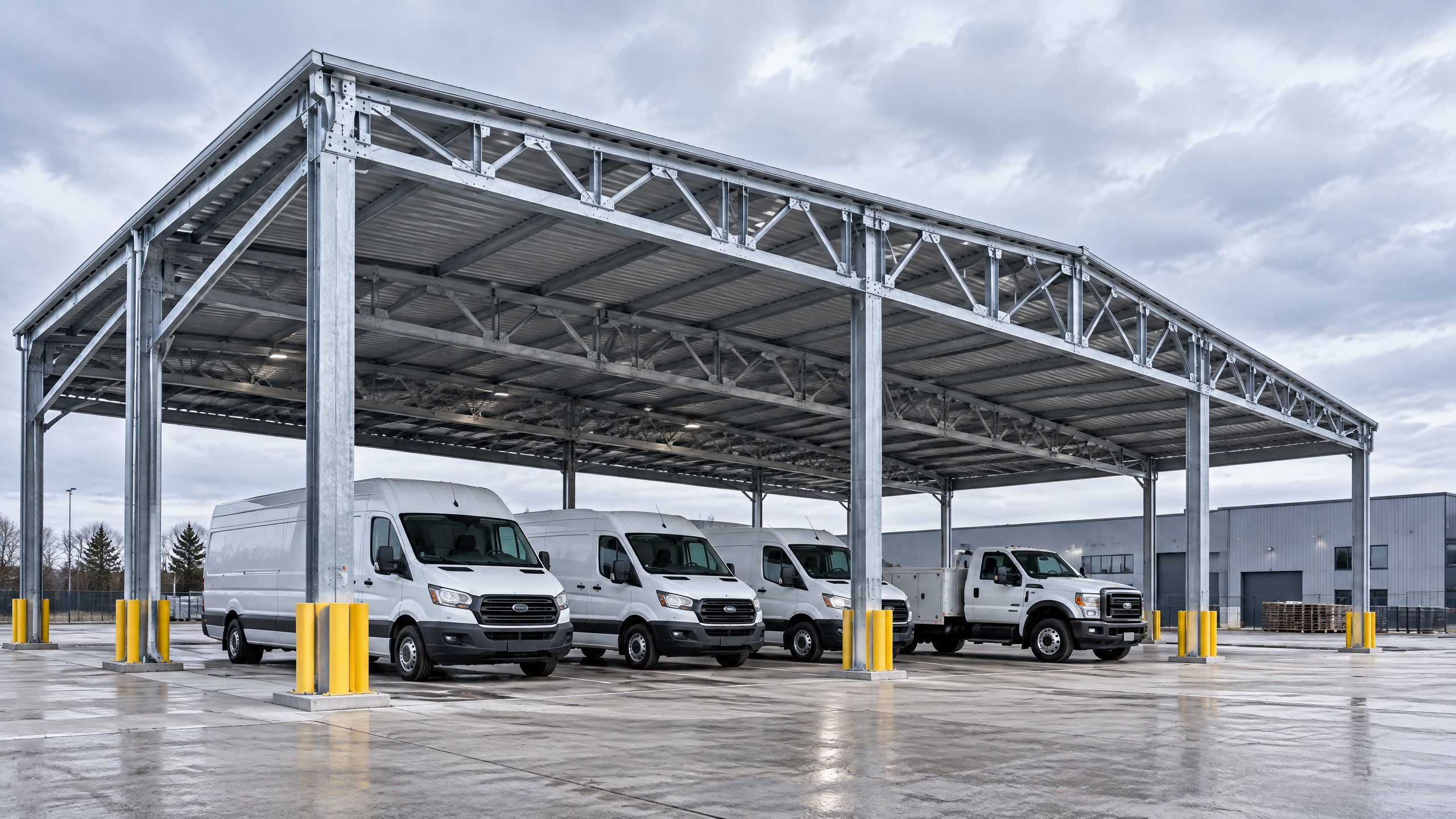
Clear, evidence-based bus depot canopy vehicle clearance is the single most important design parameter that links fleet mix, site layout, structural design and operational workflows. In practice this means fixing minimum vertical and lateral clearances from a validated vehicle inventory, applying turning and service access envelopes, and embedding those envelopes into the structural canopy specification and commercial parking layout. Good vehicle clearance planning reduces damage risk, lowers lifecycle maintenance, and preserves operational throughput; poor planning causes hold-ups, retrofit costs and safety incidents. This guide presents the procurement and implementation implications you must resolve before committing to manufacture or installation: planning inputs and survey methods, structural and electrical interfaces (including solar), procurement evidence and factory QA, an installation readiness checklist, implementation risk controls, a repeatable six-step buyer workflow and a practical FAQ. For project-specific limits (foundations, permits, energy yield, warranty and lead time) use a documented project basis and engage qualified local professionals, installers, utilities and authorities.
Buyer context and scope boundary
Purpose and audience
- Audience: distributors, architects, contractors, developers, solar EPCs and fleet operators procuring or specifying depot canopies for commercial and industrial applications.
- Primary subject: bus depot canopy vehicle clearance as the focal design, procurement and operational decision.
- Scope: above-ground canopy structures (aluminium and steel framed), vehicle maneuvering and static parking under canopies, integration with commercial solar carports, structural interfaces and site installation (but not detailed electrical design or foundation engineering).
Why clearance matters for bus depots
- Clearance dimensions determine column placement, span, and structural loads; they directly affect fleet access, maintenance operations, and charging/electrification infrastructure placement.
- Clearance influences cost drivers: higher clearances typically increase structural mass or span requirements; tighter columns increase risk of vehicle strikes and operational delays.
- Clearance decisions are not isolated — they interact with commercial parking layout, vehicle routing, and project phasing plan.
Scope boundaries and required specialists
- This guide covers decision-making, procurement evidence, specification interfaces, and practical site-readiness requirements.
- Site-specific structural capacity, foundations, permits, electrical design, approvals, lead time, price, energy yield and warranty require a documented project basis and input from relevant local qualified structural engineers, geotechnical engineers, licensed installers, utilities and permit authorities.
Core decision principle: safety and throughput first, then cost per square metre
Principle statement
- Prioritise operational safety and throughput (vehicle ingress/egress and service access) when defining bus depot canopy vehicle clearance; only after these performance metrics are fixed should you optimize for unit cost and aesthetic outcomes.
How to apply the principle
- Lock fleet and service envelope data first: vehicle heights with roof equipment, service lifts or platforms, and emergency access clearances.
- Use operational access coordination to test proposed layouts against peak movement scenarios including recovery and breakdown.
- Convert operational requirements into a structural canopy specification that the engineering team can cost and certify.
Decision trade-offs
- Higher clearance reduces fleet constraints but increases structure/bracket costs and may complicate solar PV tilt and cable runs.
- Lower clearance saves material but raises collision risk and may reduce operational resilience or future-proofs capacity (e.g., electrification with roof-top equipment).
Evidence base and risk-balancing
- Use measured fleet data and turning templates rather than typicals when possible.
- Run at least one day of simulated peak operations on CAD or BIM models to identify pinch-points before procurement.
Planning inputs: what you must collect before specifying clearance
The quality of your clearance specification is proportional to the quality of your planning inputs. Collect these items early.
- Fleet inventory and contingencies
- Detailed vehicle list: make/model, nominal height, roof-mounted equipment (AC units, monitoring, pantographs), wheelbase and overhang.
- Growth allowances: projected fleet mix and spare vehicle staging over the next 5–10 years.
- Emergency and recovery vehicle dimensions (tow trucks, service cranes).
- Operational envelopes and activity mapping
- Turning circle templates and swept path analysis for ingress/egress, tight turns and maintenance lanes.
- Static offsets for maintenance access, side-door operation, and platform lifts.
- Operational access coordination: sequences for bus marshalling, cleaning, refuelling or EV charging.
- Site survey and physical constraints
- As-built site survey: finished levels, kerb lines, drainage, existing services, and overhead utilities.
- Topographic and flood risk data (refer to regional maps such as FEMA flood maps when applicable) [2].
- Utilities run locations and legal easements.
- Regulatory and operational constraints
- Local building code clearances, egress and fire access lanes; vehicle parking guidance and accessible spaces (see parking guidance) [1].
- Construction safety requirements and temporary works considerations during installation (see OSHA construction standards) [3].
- Road/traffic interface requirements from highway authorities (FHWA guidance) where depot access intersects public roads [4].
- Electrical and energy inputs (if solar or charging)
- Charger / inverter envelope dimensions and cable entry points; electrical room locations.
- Energy yield targets (for solar), and constraints imposed by canopy tilt, orientation and shading.
- Utility interconnection ceiling and conduit entry elevations.
- Geotechnical and foundation inputs
- Subsurface conditions, allowable bearing capacity, water table depth and corrosivity.
- Foundation options: pad, continuous footing, piled foundations for high water areas.
- Programme parameters
- Required project phasing plan with milestones: procurement, factory production, site works, commissioning.
- Lead time limitations and preferred installation windows (night work, low-traffic periods).
Decision table: minimal initial dataset vs recommended dataset
| Dataset element | Minimum for initial estimate | Recommended for procurement-grade specification |
|---|---|---|
| Fleet heights and roof items | Approx heights by vehicle class | Measured heights per vehicle with roof equipment and future growth list |
| Site survey | Boundary plan | Topographic, underground utilities, flood elevations |
| Geotech | Anecdotal soil notes | Boreholes, lab reports, groundwater table |
| Regulatory context | Knowledge of local codes | Permit pre-application notes and fire service input |
| Electrical | General power demand | Charger/inverter envelopes, conduit routes, utility application constraints |
Technical specification and interfaces
Transform planning inputs into clear technical deliverables. This section sets the minimum content for a structural canopy specification and associated interface drawings.
Must-have elements in the structural canopy specification
- Design clearance envelope: defined plan and elevation envelopes with an agreed datum (e.g., finished floor level or carriageway top).
- Structural canopy specification: materials (aluminium grade or coated steel), wind and snow load cases, design life, corrosion protection, connection details, and column sizes and locations.
- Foundation interface: recommended pile/pad scheme with reference bearing pressures (design anchorages to be confirmed by local geotechnical engineer).
- Column protection detailing: bollards, wheelstops, and passive guardrail locations.
- Roofing and drainage: roof type (membrane, seamless panels), gutter positions and downpipes; incorporate roof-mounted equipment access and clearances.
- Electrical and trunking interfaces for chargers and solar: specified knockouts and cable entry points, minimum riser clearances and location of inverter/DB.
Vertical and lateral clearances — practical guidance
- Define two vertical clearances:
- Operational clearance (minimum): clearance required for safe passage without additional safety margin.
- Absolute clearance (recommended design): operational clearance plus a buffer (commonly 300–500 mm depending on fleet and site constraints) to allow for dynamic loading, road hump variations and driver error.
- Lateral clearance: clear distances from column face to vehicle side and door swing areas, including maintenance access.
Interface drawings and tolerances
- Provide a plan and elevation of vehicle envelope overlaid on structural grid at procurement stage.
- Tolerances for column position (typically ±25–50 mm depending on foundation type) must be documented and accepted before fabrication.
- Define erection interfaces: crane lift points, temporary anchorage loads, and approved lifting access.
Decision table: sample clearance envelopes by bus type (illustrative — confirm with measured fleet data)
| Bus type | Typical roof equipment | Minimum operational clearance (mm) | Recommended design clearance (mm) |
|---|---|---|---|
| Standard single-deck bus | Low-profile AC units | 3,200 | 3,500 |
| Articulated bus | Roof vents, ADAS antennas | 3,700 | 4,100 |
| Double-deck bus | Roof-mounted HVAC, signage | 4,400 | 4,800 |
| EV bus with rooftop pantograph | Pantograph raised position | 4,500 (stowed) / verify raised | 5,000+ (depends on pantograph spec) |
Notes: the table is an aid. Do not substitute measured vehicle heights and roof equipment profiles. Pantograph and charging equipment require manufacturer envelopes.
Solar and electrification interfaces
- If adding PV, coordinate panel tilt and inverter positions with clearance and service access. Higher clearances can marginally reduce PV packing density and raise array costs.
- Define cable tray routes and minimum bend radii; provide commissioning access near inverters and chargers.
- For charger infrastructure include service clearance around charging units for maintenance and ventilation.
Materials and finish considerations affecting clearance
- Column guarding and fenders add to effective footprint — include allowances in vehicle clearance planning.
- Roof overhangs and fascia may reduce lateral clearance; define these in the interface drawings.
Procurement and factory evidence: what to ask suppliers
Procurement-grade evidence ensures the product you order will match site realities on delivery and installation.
Mandatory technical documents to request
- Full structural drawings stamped by a licensed engineer for the jurisdiction of manufacture and intended installation.
- Bill of Materials (BOM) and material certificates (e.g., aluminium alloy designation and finish, or steel grade and coating).
- Welding and fabrication QA procedures; evidence of factory inspection regimes.
- Manufacturing tolerances, connection details and column anchor arrangement drawings.
- Factory load testing or calculation reports for connection details (if available) — note: do not accept generic claims; ask for project-specific calculations.
- Delivery and installation method statement, including temporary works and lifting plan.
- Factory acceptance checklist and photographs of representative completed units.
Quality checkpoints and factory audit focus areas
- Dimensional control: verify that column spacing and module lengths match your interface drawings and erection tolerances.
- Surface treatment and corrosion protection: check samples and test reports for coatings or anodizing.
- Fastener specification and bolt grades; verify torque and embedment recommendations.
- Weld reports and non-destructive testing where critical welds are load-bearing.
Commercial and contractual levers
- Include acceptance criteria for installation readiness: “No-install” penalties for late manufacturing that impact factory-to-site coordination should be clearly defined.
- Define hold points: factory inspection, delivery inspection, foundation accept, final erection, and commissioning.
- Require as-built drawings and O&M manuals upon completion.
Factory evidence checklist (decision-oriented)
| Evidence item | Purpose | Accept / Reject criteria |
|---|---|---|
| Stamped structural drawings | Confirm structural adequacy | Stamp from licensed engineer; project-specific load cases |
| Material certificates | Verify corrosion resistance and grade | Certificates traceable to batch number |
| Fabrication QA procedures | Manufacturing quality control | ISO or equivalent QA demonstrated |
| Erection method statement | Installation safety and sequence | Includes temporary works and crane lifts |
| Warranty and exclusions | Risk allocation | Clear term and exclusions; energy yield/warranty to be project-specific |
Site installation and operations: achieving installation readiness
Installation readiness is the bridging stage between procurement and reliable operation. Define deliverables and responsibilities clearly.
Pre-installation: site readiness tasks
- Foundations certified by local geotechnical/structural engineer and tolerances measured and recorded.
- Utilities marked and protected; temporary diversion plans where necessary.
- Traffic management plan for site access during installation with stakeholder notifications.
- Crane positions and ground bearing plans approved.
Installation sequence and typical constraints
- Sequence: foundations → column erection → primary beams → roofing → electrical and ancillary works → commissioning.
- Night or weekend installs may be required to avoid operational disruption; coordinate with operations and authorities.
- Mechanical connectors, grout and torqueing must be verified at time of erection.
Installation readiness checklist
- Confirm foundation positions within fabrication tolerances and provide survey certificates.
- Verify column protection measures and pass-through routing of services.
- Check that lifting equipment and cranes have the required SWL (safe working load) certificates and ground matting.
- Establish site-based QA sign-offs and hold points.
Operations handover and commissioning
- Perform clearance verification by driving representative vehicles through key routes prior to full handover.
- Record any as-built deviations and produce an agreed snip list for remedial work.
- Institute a short-term defect liability observation period and scheduled inspection regime for critical connections and column guards.
Maintenance and lifecycle considerations
- Provide inspection schedule and maintenance access points for roof cleaning, PV maintenance and drainage clearing.
- Plan for periodic clearance re-checks after resurfacing or kerb modifications that may change vehicle datum elevations.
Mid-article CTA Discuss your depot clearance and canopy requirements with our team: /inquiry or info@carportiva.com
Implementation risk: common problems and mitigations
Risk is inevitable; effective mitigation is a procurement and design discipline.
Risk: incomplete fleet data leading to inadequate clearances
- Mitigation: require measured vehicle heights and a signed fleet declaration; incorporate growth allowances and a formal change control for fleet updates.
Risk: foundation tolerances mismatch to fabricated column layout
- Mitigation: agree tolerance band and perform a pre-pour set-out audit; where possible manufacture baseplates that allow for minor adjustment.
Risk: clashes with underground utilities or drainage routes
- Mitigation: include non-intrusive ground penetrating radar (GPR) as part of site survey; verify with utility providers.
Risk: factory production delays impact phased occupation
- Mitigation: build a project phasing plan with defined scope for temporary works and partial openings; include staged deliveries.
Risk: electrical design conflicts for PV and charging
- Mitigation: early integration meeting between canopy supplier, electrical engineer and utility; define electrical access spines before final fabrication.
Risk: safety incidents during erection
- Mitigation: enforce site-specific safety plan per OSHA or equivalent jurisdictional requirements; require certified temporary works designers for lifts and scaffolds (see [3] for construction regulations).
Risk: warranty disputes
- Mitigation: clarify warranty scope at procurement; require manufacturer to provide evidence-based exclusions and to submit test documentation where performance is claimed.
Risk and mitigation summary table
| Risk | Likelihood (subjective) | Primary mitigation |
|---|---|---|
| Wrong vehicle envelopes | Medium | Measured fleet data and signed approvals |
| Foundation misalignment | Medium | Pre-pour setting checks and adjustable baseplates |
| Hidden services | Medium | GPR and utility confirmation |
| Delayed manufacture | Medium | Phased plan and contractual penalties |
| Electrical interface conflict | Low–Medium | Early multi-discipline coordination |
Six-step buyer workflow for bus depot canopy vehicle clearance
This named workflow converts the guidance above into an executable process for procurement teams.
- Capture and validate operational inputs
- Collect measured vehicle dimensions, roof equipment lists, and operational sequences. Confirm with fleet operator.
- Site and regulatory due diligence
- Commission full topographic survey, geotechnical investigation and regulatory pre-application with local authorities.
- Develop vehicle clearance and layout model
- Produce swepth-path analyses and overlay the vehicle envelopes on the proposed commercial parking layout. Agree operational clearance and absolute design clearance.
- Define interfaces and procurement specification
- Prepare a structural canopy specification with column grids, foundation constraints, electrical knockouts and interface tolerances. Include structural canopy specification clauses and acceptance criteria.
- Procurement, factory verification and QA
- Tender with mandatory factory evidence, hold points and acceptance criteria. Conduct factory audits and review stamped drawings before release to manufacture.
- Coordinate installation and commissioning
- Execute project phasing plan, verify foundation tolerances, perform erection per method statements, conduct clearance verifications and handover with agreed snag list.
Checklist per step: sign-off criteria
- Step 1: signed fleet declaration and operational approval.
- Step 2: survey and geotech delivered; permit pre-application comments logged.
- Step 3: clearance model accepted by stakeholders.
- Step 4: procurement-ready spec and interface drawings issued.
- Step 5: factory evidence accepted; production released.
- Step 6: installation readiness confirmed; final commissioning tests passed.
Link back to systems and guides
- For modular options and alternative configurations evaluate our Titan industrial and logistics system and explore all systems. For procurement templates and checklists, see our sourcing guides.
FAQ
Q: What is the appropriate clearance buffer above measured vehicle height? A: Buffer typically ranges 300–500 mm as a design safety tolerance; however, the exact buffer is a project decision depending on fleet variability, dynamic deflection allowances and local codes. Always verify against measured vehicle heights and roof equipment.
Q: Do I need higher clearance if I intend to add solar PV? A: Not necessarily — many PV carports are designed around the same clearance envelopes — but higher clearances may be required if rooftop PV access equipment or pantographs for charging are expected. Plan electrical and maintenance access early.
Q: How do I handle articulated buses or vehicles with raised equipment? A: Use specific swept path templates and the maximum raised position of any rooftop device. Where raising occurs (e.g., pantographs), define operational rules for when raised positions may be used beneath canopies.
Q: Who is responsible for foundation design and permits? A: Foundations and permits are the responsibility of the project client and their appointed local qualified engineers and authorities. This guide requires their input for site-specific decisions.
Q: Are there standard clearance heights I can use for early estimates? A: You can use standardised class envelopes for early budgetary planning, but you must replace them with measured vehicle data for procurement-grade specifications.
Q: What documentation should I expect at handover? A: As-built drawings, material certificates, QA and test records, maintenance manual, and a certified clearance verification report demonstrating vehicles can safely operate as designed.
Q: Where can I find guidance about accessible parking and aisle dimensions? A: Refer to the U.S. Access Board parking guidance for accessible parking dimensions and layout considerations [1].
Conclusion
Bus depot canopy vehicle clearance is a technical decision with commercial and operational consequences. Making it the controlling parameter — by capturing accurate vehicle data, integrating operational access coordination into layout, and translating those needs into a precise structural canopy specification — reduces retrofit costs, supports safe operations and enables productive procurement. Use the six-step buyer workflow to convert site data into procurement-ready specifications, insist on factory evidence and stamped drawings, and require documented installation readiness as a condition for handover. Remember: site-specific structural capacity, foundations, permits, electrical design, approvals, lead time, price, energy yield and warranty require a documented project basis and involvement from relevant local qualified professionals, installers, utilities and authorities.
For help with project-level scoping or to review a draft specification, contact us: /inquiry or info@carportiva.com
References
- U.S. Access Board parking guidance: https://www.access-board.gov/ada/guides/chapter-5-parking/
- FEMA flood maps: https://www.fema.gov/flood-maps
- OSHA construction standards: https://www.osha.gov/laws-regs/regulations/standardnumber/1926
- Federal Highway Administration: https://highways.dot.gov/
Keep the project brief connected.
Bring the actual project brief to the engineering table.
Share your location, layout, target application and available technical inputs. Carportiva can help identify the relevant product-interface information before a project-specific commercial discussion.
Request a project discussion