Direct answer (120–180 words)
A project team should confirm that the proposed commercial parking canopy structural system satisfies site-specific load cases, vehicle operational needs, and project delivery constraints before committing to procurement. At minimum this means validated structural calculations for local wind, snow, seismic and flood conditions; a foundation strategy compatible with geotechnical data; clear interfaces for PV, lighting and drainage; confirmed vehicle clearance and commercial parking layout requirements; coordination with utilities and emergency access; and documented factory and installation evidence (material certificates, shop drawings and installation readiness plans). Procurement should also require a project phasing plan, quality assurance milestones and installation readiness verification to align lead times and contractor availability. Site-specific structural capacity, foundations, permits, electrical design, approvals, lead time, price, energy yield and warranty all require a documented project basis and engagement of relevant local qualified professionals, installers, utilities and authorities.
Buyer context and scope boundary
Why this matters for commercial and industrial applications
A commercial parking canopy structural system is a long-life, engineered asset that affects site circulation, safety, operational access coordination, stormwater performance and, where fitted, energy production. In commercial and industrial applications—retail centres, office campuses, industrial parks, logistics yards and fleet depots—the canopy is both infrastructure and operational enabler. Buyers (distributors, architects, contractors, developers, solar EPCs, fleet operators) must set clear scope boundaries early:
- Define whether the system is purely structural (shelter/architectural aluminium), a PV carport, or a hybrid that includes lighting, EV charging, signage and access-control ancillaries.
- Establish performance requirements: vehicle clearance, load capacity, clear span vs. column grid, and durability expectations for the location.
- Clarify responsibility split between supplier, civil contractor and electrical/utility contractor for foundations, trenching and electrical interconnection.
Note: Site-specific structural capacity, foundations, permits, electrical design, approvals, lead time, price, energy yield and warranty require a documented project basis and relevant local qualified professionals, installers, utilities and authorities.
Decision boundary checklist (quick)
- Is this a standalone architectural aluminium carport, a commercial solar carport, or an industrial fleet shelter?
- Who delivers foundations and who is responsible for connection to local utilities?
- What acceptance criteria will the owner use at handover?
Core decision principle
Choose the structural solution that minimises operational disruption while meeting life-cycle value
The central procurement principle is to select the commercial parking canopy structural system that achieves the required operational outcomes at lowest total project risk and lifecycle cost—not merely lowest initial price. For commercial and industrial projects, this means balancing:
- Operational access coordination and vehicle clearance planning with structural geometry and column placement.
- Structural canopy specification (materials, coatings, connection design) matched to the local environment and intended maintenance resource.
- Implementation constraints such as available crane size, site phasing and on-site storage.
A systems-based decision (e.g., choosing a product family like Titan industrial and logistics system or selecting from all systems) should be preceded by verification of interfaces and risks on the specific site.
Planning inputs: what the project team must collect
Accurate inputs are non-negotiable for safe, cost-effective results. The following are minimum planning inputs required to develop and approve a structural canopy design and procurement pack.
Site and context
- Site plan with contours, thresholds, existing utilities and known obstructions (light poles, trees).
- Geotechnical report that includes bearing capacity, groundwater table, and recommendations for shallow/deep foundations.
- Floodplain or local flood risk mapping for foundation and elevation decisions (see FEMA flood maps) [2].
Operational requirements
- Commercial parking layout showing parking bay dimensions, drive aisles and pedestrian routes.
- Vehicle clearance planning including maximum vehicle height, turning templates for service and delivery vehicles, and tracking for trucks or forklifts.
- Loading/unloading zones and emergency vehicle access; any needs for covered operational bays.
Regulatory and code inputs
- Relevant local building codes for structural design (wind, snow, earthquake) and construction safety (work options should follow OSHA standards during construction) [3].
- Accessibility requirements for accessible parking and aisle layouts (see U.S. Access Board guidance for parking) [1] where applicable.
- Roadway/curb and crossfall constraints referenced against local highway authority guidance (FHWA) [4].
Electrical and PV design (if relevant)
- Utility point of connection, metering strategy, and fuse/transformer capacity.
- Expected module layout, inverter locations and DC string lengths when PV is included; preliminary energy yield expectations from EPC.
Timeline and procurement constraints
- Required operational start date, phased occupancy dates and any constraints on night/time works.
Stakeholder list
- Owner, architect, civil/structural engineer, electrical/EPC contractor, main contractor, local authority contacts and supplier(s) for canopy.
Technical specification and interfaces
Define the structural canopy specification and how it interfaces with adjacent systems
A comprehensive structural canopy specification should include materials, load combinations, connections, tolerances and interfaces with electrical, drainage and other building systems.
Structural elements and materials
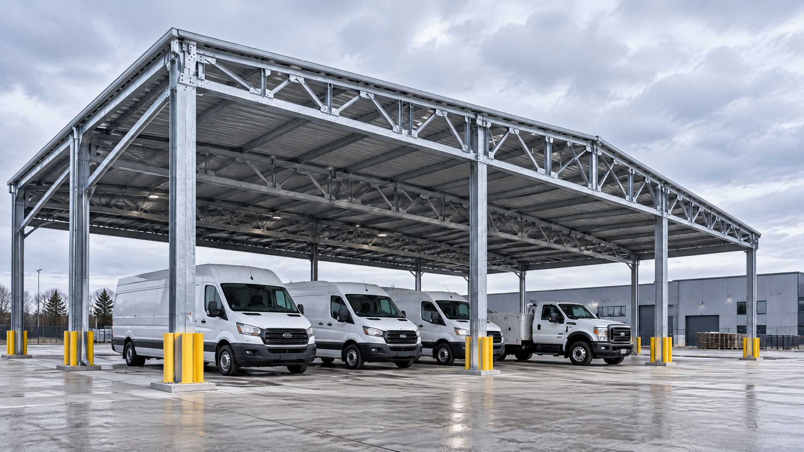
- Primary structure: columns, beams and any truss or portal frames. Indicate grade and finish (e.g., architectural aluminium alloy series, anodising or powder coat).
- Secondary structure: purlins, membrane or decking support systems; specify section sizes and connection details.
- Fasteners and connections: materials, protective finishes and bolt grades. Consider galvanic compatibility between aluminium and steel elements.
Design loads and analysis
- Design values for live loads, wind loads, snow loads and seismic forces per local code.
- Consider uplift and overturning at column bases; specify baseplate design and moment transfer mechanism.
- Drainage loads for snowmelt and rainwater; include gutter and downpipe details.
Foundations and groundworks
- Foundation types (pad, pile, strip) must be correlated to geotechnical recommendations.
- Seismic base isolation or detailing if required by code.
- Foundation top-of-concrete tolerance that affects column height and canopy levelness.
Interfaces: electrical, drainage, lighting, and EV infrastructure
- Mounting points for PV modules and cable routes; specify conduit sizes and junction box locations.
- Lighting and trunking integration; location of access panels for maintenance.
- EV charger mounting options and cable containment.
Serviceability and durability
- Deflection limits for serviceability—limit criteria tied to glazing or PV module manufacturer recommendations.
- Corrosion protection strategy and maintenance intervals tailored to site environment (coastal chloride exposure demands different finishes than inland industrial).
Vehicle, pedestrian and operational interfaces
- Vehicle clearance planning must be explicit: specify minimum clearances and tolerances (roof height, soffit or gutter projection) to accommodate all vehicle classes using the facility.
- Pedestrian safe zones, bollard coverage and signage mountings.
Structural canopy specification sample checklist
- Material grades and finishes
- Design load assumptions and referenced codes
- Foundation compatibility and tolerances
- Interface points for electrical/PV and lighting
- Installation tolerances and adjustment mechanisms
Decision table 1 — Structural form suitability
| Structural form | Typical span range | Operational fit (vehicle clearance & layout) | Pros | Cons |
|---|---|---|---|---|
| Column grid (regular bays) | 6–12 m | Best for standard parking bays; easy column alignment with bays | Simple design, predictable foundations, modular | Columns can obstruct some manoeuvres; less continuous canopy |
| Cantilevered bays | 6–10 m | Useful for pedestrian canopies or where columns impede operations | Clear access zone under canopy edge | Limited span; higher moment at supports |
| Long-span portal frames | 12–20 m+ | Suitable for fleet yards and loading areas needing unobstructed space | Fewer columns, wide unobstructed areas | Heavier members, deeper foundations, higher cost |
| Roof-on-frame (low profile) | Variable | Good for aesthetic sites with solar integration | Easier PV mounting, lower profile | May limit clearance without larger frame |
Use this table to match the canopy type to your commercial parking layout and vehicle clearance planning needs.
Procurement and factory evidence required
What to demand from suppliers before award
To de-risk delivery, procurement documents should require verifiable factory evidence and key deliverables at procurement milestones. Minimum evidence items:
- Detailed shop drawings and structural calculations stamped by a qualified engineer for the jurisdiction or by a competent design authority.
- Material certificates for primary members, fasteners and coatings (e.g., metal grade certificates, mill certificates).
- Welding procedure specifications and welder qualifications where welding forms a key connection.
- Factory acceptance test (FAT) criteria for mechanical assemblies, kinematic elements and electrical ancillaries.
- Production schedule with committed lead times and contingency plans for long-lead items.
- Packaging and delivery plan, including lifting points and on-site handling requirements.
- Installation readiness package that includes pre-assembly checks, as-built tolerances and health & safety method statements.
Decision table 2 — Procurement evidence checklist
| Evidence item | Why required | Minimum acceptance criteria |
|---|---|---|
| Structural calculations | Verify safety and compliance | Calculations stamped by qualified engineer, load combinations per project code |
| Shop drawings | Ensure fit-up and interface clarity | Full dimensions, connection details, foundation interfaces |
| Material certificates | Traceability and durability | Mill certs matching specified grades/coatings |
| FAT/assembly reports | Mechanical integrity before shipping | Signed FAT with pass/fail criteria and corrective actions |
| Welding PQR/WPS | Connection quality | WPS and qualified welders per standard |
| Transport & lift plan | Safe delivery and installation | Method statement, sling points, crane specs |
| Installation readiness | Reduce site delays | Tools/materials list, sequence, manpower plan |
Factory inspection and QA
- Agree on rights for owner or third-party inspections during fabrication and pre-shipment.
- Include non-conformance reporting and remedy timelines in contract terms.
Remember: lead time, price and warranty terms require a documented project basis and verification with local professionals.
Mid-article CTA
If you need a vendor that can supply structural options or assist with a detailed procurement pack, contact /inquiry or info@carportiva.com. See Titan industrial and logistics system for a product family and review all systems and our sourcing guides for procurement templates.
Site installation and operational readiness
Preparing the site and ensuring installation readiness
Installation readiness is a combination of logistic planning, site preparation and on-site coordination. An Installation Readiness (IR) checklist reduces surprises:
Pre-installation
- Confirm foundations are constructed to tolerance; verify top-of-foundation elevation and anchor bolt positions against shop drawings.
- Ensure onsite storage area is identified with load capacity and weather protection.
- Confirm crane access routes and ground bearing capacity; arrange traffic management if lifting near live lanes.
On the installation day
- Hold a pre-lift meeting with all contractors and the lift supervisor. Review crane chart, lift plan and exclusion zones.
- Implement traffic and pedestrian control, temporary lighting for night works and emergency procedures.
- Verify ambient conditions for coatings or adhesives; maintain manufacturer-specified temperature/humidity.
Testing and handover
- Conduct alignment and level checks; torque checks on anchor bolts and structural bolting.
- Functional tests for integrated electrical, lighting and PV systems (if applicable) should be coordinated with the electrical contractor.
- Issue as-built documentation, warranties and an operations and maintenance manual.
Operational access coordination
- Confirm operational access coordination with fleet managers and tenants: staging plans during installation, phased handovers where required, and protection of critical operations.
- For fleet and logistics sites, maintain contingency plans for rerouting vehicles and adjust shift patterns if works affect peak operations.
Maintenance planning
- Provide a lifecycle maintenance schedule for protective finishes, fastener checks, and cleaning of PV modules/drainage points.
Note: Site-specific approvals and electrical design coordination must involve local utilities and qualified electrical designers.
Implementation risks and mitigation
Common risks and practical mitigation strategies
- Foundation mismatch with geotechnical assumptions
- Risk: Foundations do not match bearing capacity or unexpectedly high groundwater causes pile requirements.
- Mitigation: Require geotechnical report early; include site-specific allowance in budget; add contingency for alternate foundation types.
- Column locations that obstruct operational flows
- Risk: As-built column grid impedes required vehicle turning radius.
- Mitigation: Early vehicle clearance planning with swept-path analysis, ensure shop drawings are coordinated with as-built parking layout.
- Delayed lead times for long-lead items
- Risk: Extended fabrication lead times delay occupancy.
- Mitigation: Secure production slots, include milestone payments tied to production progress, consider alternate suppliers or modular options.
- Incompatibility with electrical/PV designs
- Risk: Module layout or inverter placement clashes with structural supports.
- Mitigation: Co-design sessions between structural and electrical engineers; include conduits and cable trays in early interface drawings.
- Weather-related installation interruption
- Risk: Heavy rain or wind delays lifts and concreting.
- Mitigation: Plan seasonal windows for installation, include weather allowance in project phasing plan.
- Regulatory approvals delays
- Risk: Permitting takes longer than anticipated.
- Mitigation: Early engagement with local authorities and submission of preliminary drawings to identify key constraints.
- Safety incidents during construction
- Risk: Injury or damage due to inadequate site controls.
- Mitigation: Enforce OSHA-aligned construction safety practices, permit-to-work for lifts, and toolbox talks.
- Warranty and post-handover disputes
- Risk: Disagreement over scope of warranty work and responsibility.
- Mitigation: Clear contractual definitions for warranty terms and exclusions; require documented pre-handover condition reports.
A named six-step buyer workflow: The Canopy Assurance Workflow
This workflow is designed for buyers to follow from brief to handover to reduce procurement and implementation risk.
Step 1 — Define the operational brief
- Deliverable: A concise requirement document outlining parking capacity, vehicle types, operational hours, PV expectations, and phasing constraints.
Step 2 — Collect technical inputs
- Deliverable: Site plan, geotechnical report, utility info, planning constraints, and any accessibility requirements. Commission swept-path diagrams for heavy vehicles.
Step 3 — Select system family and preliminary layout
- Deliverable: A shortlist of compatible system families (e.g., Titan industrial and logistics system and others from all systems), preliminary spans and structural form, estimated budgets.
Step 4 — Detailed design and procurement pack
- Deliverable: Shop drawings, structural calculations, foundation drawings, interface drawings with electrical/PV, performance specifications and procurement contract with required factory evidence.
Step 5 — Factory QA and site installation readiness
- Deliverable: Material certificates, FAT reports, delivery and lift plans, confirmation of installation readiness including on-site storage and crane permits.
Step 6 — Commissioning and handover
- Deliverable: As-built drawings, operation & maintenance manual, test reports for electrical/PV systems, warranty documentation and a clear punch-list acceptance process.
Each step should have acceptance criteria and a sign-off by the appointed responsible party.
Frequently asked questions (FAQ)
Q: How high above finished vehicle surface should a commercial parking canopy be for standard cars and delivery vans? A: Minimum clearances depend on the vehicle fleet. For typical passenger cars, 2.1–2.4 m soffit clearance is common; for delivery vans allow 2.7–3.0 m; for light trucks or forklifts the clearance must be determined by vehicle envelope and include allowance for signage and lighting. Always confirm vehicle clearance planning with swept-path analysis.
Q: What codes should structural design reference? A: Use the applicable local structural, wind, snow and seismic codes. For construction safety during installation incorporate OSHA construction standards into the installation method statement [3]. For accessible parking layout, consult guidance such as the U.S. Access Board where relevant [1].
Q: Who is typically responsible for foundations? A: Responsibility should be defined in the contract. Common approaches: owner supplies foundations via civil contractor; supplier supplies foundation design with owner to procure works; or supplier offers turnkey delivery including foundations. Each option transfers different risks—document them.
Q: How are PV arrays integrated without compromising structural performance? A: PV integration must be treated as a service load. The structural canopy specification should include PV dead loads, concentrated loads from modules and racking, and wind uplift considerations for module edges. The electrical route planning and inverter placement must be included in early drawings.
Q: What factory evidence is critical before shipment? A: Stamped structural calculations, shop drawings, material mill certificates, FAT reports, welding qualifications and packaging/transport plans are key. These reduce the risk of rework on site.
Q: Can canopies be phased for partial occupancy? A: Yes. A project phasing plan should define areas to be completed first, temporary access arrangements and acceptance criteria per phase. Phasing requires careful traffic management and possibly interim structural loads.
Q: Are there particular considerations for coastal or corrosive environments? A: Yes. Specify materials and protective finishes suitable for chloride exposure. Consider aluminium alloys with appropriate anodizing or higher-grade coatings and ensure stainless fasteners where dissimilar metals could cause galvanic corrosion.
Q: How to handle unknown subsurface conditions discovered during foundation works? A: Have contract provisions for unforeseen ground conditions, contingency time and budget. Engage geotechnical specialists to reassess and recommend remediation or alternate foundation systems.
Q: What about warranties and performance guarantees? A: Warranties should be specific and limited in scope and duration. Ensure inclusion of manufacturer warranties for materials and separate supplier warranties for workmanship. Energy yield guarantees for PV require separate contractual arrangements and verified energy modelling.
Q: Who needs to sign off on structural calculations? A: A qualified structural engineer licensed in the project jurisdiction must review and stamp the calculations. This may be the supplier’s engineer, the owner’s retained engineer or the local authority depending on contract and code requirements.
Conclusion
A successful commercial parking canopy structural system procurement depends on detailed, coordinated planning that aligns operational needs, design loads and delivery constraints. The project team should confirm vehicle clearance planning, operational access coordination, structural canopy specification and installation readiness early; require verifiable factory evidence; and follow a defined procurement and installation workflow to minimise schedule and warranty risk. Use the six-step Canopy Assurance Workflow to structure reviews and approvals, and make sure site-specific structural capacity, foundations, permits, electrical design, approvals, lead time, price, energy yield and warranty are confirmed on a documented project basis with relevant local qualified professionals, installers, utilities and authorities.
For further specification support, product options or procurement templates see sourcing guides or contact /inquiry or info@carportiva.com.
References
- U.S. Access Board parking guidance: https://www.access-board.gov/ada/guides/chapter-5-parking/
- FEMA flood maps: https://www.fema.gov/flood-maps
- OSHA construction standards: https://www.osha.gov/laws-regs/regulations/standardnumber/1926
- Federal Highway Administration: https://highways.dot.gov/
Keep the project brief connected.
Bring the actual project brief to the engineering table.
Share your location, layout, target application and available technical inputs. Carportiva can help identify the relevant product-interface information before a project-specific commercial discussion.
Request a project discussion