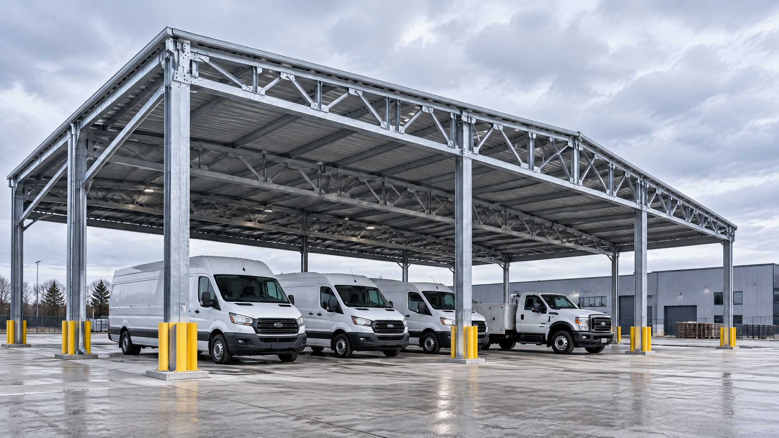
Fleet carport vehicle clearance matters at every stage of a commercial or industrial carport project where vehicles, operations, personnel or equipment interface with a canopy or shelter. Correct clearance planning avoids vehicle damage, operational delay, unsafe work zones, permit refusals and retrofit costs. This short guide explains when clearance is the primary driver of design decisions, how to turn fleet data into procurement specifications, what technical and site inputs are required, and which procurement and installation controls will prove the specification in manufacture and on site. It is focused on evidence-led decisions for distributors, architects, contractors, developers, solar EPCs and fleet operators considering aluminium architectural carports, commercial solar carports and industrial/fleet shelters. Use this guide to identify when clearance is a constraint that triggers changes to the commercial parking layout, structural canopy specification, operational access coordination and broader project phasing plan.
Buyer context and scope boundary
Why focus on clearance?
- Clearance is the spatial gap between vehicle extremities (including load, rooftop equipment and dynamic movement) and the finished underside or elements of a carport. In fleet contexts this gap is often smaller than for retail or public parking because of larger vehicles, rooftop equipment and high-frequency operations.
- When clearance governs decisions: where fleet vehicles, loading operations, crane lifts, high-side signage, battery replacement equipment, or rooftop solar servicing intersect with canopy structures; where vertical or lateral constraints are tight; and where vehicle height or dynamic envelope varies across the fleet.
Who should use this guide?
- Distributors specifying resell systems and warranty terms.
- Architects integrating carport structures into masterplans where vehicle access and clearance influence building interfaces.
- Contractors preparing site civil and foundation works where clearance affects foundation positions.
- Developers and facility managers balancing throughput, lease conditions and service vehicle access.
- Solar EPCs and integrators designing PV arrays that must allow access for taller vehicles and maintenance equipment.
- Fleet operators aligning parking geometry with turnaround times and safety requirements.
Scope boundary and assumptions
- This guide covers commercial and industrial applications where fleet carport vehicle clearance is the primary design constraint. It addresses planning inputs, specification, procurement verification, installation coordination and post‑installation operations.
- It does not replace site‑specific structural engineering, electrical design, local permitting, foundation design, or utility coordination. Site-specific structural capacity, foundations, permits, electrical design, approvals, lead time, price, energy yield and warranty require a documented project basis and relevant local qualified professionals, installers, utilities and authorities.
Core decision principle
Make clearance decisions based on the operational envelope: define the required vertical and lateral envelope for the tallest and widest vehicle movement expected, add objective tolerances for dynamic motion and maintenance access, and then derive the structural canopy specification and parking layout constraints from that envelope.
Key aspects of the principle
- Operational envelope: the vehicle body plus rooftop attachments, articulated components, and any temporary loads (ladders, service equipment, snow).
- Dynamic allowance: movements caused by suspension travel, slope, ramp gradients, loading/unloading, and driving speed. These influence minimum vertical clearance and overhang considerations.
- Service envelope: space needed for routine servicing, emergency access, and PV maintenance where applicable.
- Clearance as a constraint variable: treat clearance like a hard dimension—document it, verify with measurements, and include it in procurement drawings and acceptance criteria.
When clearance becomes the gating factor
- When the required envelope reduces net usable parking spaces, forces non-standard foundations, or requires custom canopy heights and beam depths.
- When canopy structural members or electrical conduits intersect the operational envelope and cannot be repositioned within tolerances.
- When future fleet change (e.g., transition to taller EV service vehicles) is likely and drives a different specification to avoid early obsolescence.
Decision consequence mapping
- Small clearance shortfall → minor canopy raise or reduced parking density.
- Moderate shortfall → bespoke post heights, altered column locations, or bespoke structural canopy specification.
- Large shortfall → redesign of commercial parking layout or alternative parking solutions.
Planning inputs: what you must collect before specifying clearance
To move from an operational requirement to an unambiguous procurement document, gather the following inputs.
- Fleet inventory and measured dimensions
- For each vehicle type: manufacturer declared height, roof accessories (air con, ladders, racks), maximum loaded height, wheelbase and overhangs. Where possible, perform on‑site measurements of the tallest in-service vehicle.
- For leased or mixed fleets, use a conservative ‘worst-case’ height for specification.
- Use patterns and frequency
- Typical ingress/egress angles, peak periods, and dwell times. High-frequency sites require tighter controls on rub margins; low-frequency sites may accept tighter tolerances with speed control.
- Manoeuvre paths and turning radii
- Swept-path drawings or swept-volume models for largest vehicles. Include trailer combinations where applicable.
- Site gradients, ramps and obstacle profiles
- Ramp approaches alter dynamic clearance (suspension sag/ride height changes). Capture longitudinal and cross slopes for the area under any canopy.
- Service and emergency requirements
- Access needs for forklifts, tow trucks, aerial work platforms, and maintenance vehicles; clear routes for emergency vehicles.
- PV and electrical systems design constraints
- Module tilts, cable trays, conduit runs and inverter locations. For solar carports, include access requirements for cleaning and module replacement.
- Local codes, accessibility and environmental risk
- Accessibility requirements for disabled parking [1]; flood zone elevation data [2]; construction safety standards [3]. Confirm local codes with authorities early.
- Long‑term fleet strategy
- Anticipate changes in fleet composition over the intended service life of the canopy (10–30 years for aluminium structural systems).
Collecting and validating inputs
- Require an as-built or measured survey for existing sites. For new-builds, include the fleet specification and projected vehicle types in the tender package.
- Use digital modelling (BIM or CAD) to integrate vehicle envelopes with the proposed Titan industrial and logistics system or other systems in the all systems catalogue.
Technical specification and interface requirements
Translate planning inputs into clear technical clauses and interface diagrams that a manufacturer, fabricator and installer can accept and demonstrate compliance against.
- Clearance definitions to include in the contract
- Minimum clear height under the lowest structural element (e.g., underside of canopy beam or service cable tray).
- Minimum lateral clearance from columns and fixed obstacles to vehicle body and mirrors.
- Required approach clearances to ensure dynamic envelope is preserved on ramps and bleeds.
- Tolerances and measurement methods
- Specify how clearance will be measured for acceptance (e.g., vertical measurement at mid-span, lateral at wheel track centreline), including acceptable construction tolerances (±mm).
- Define measuring time (post-installation, with finishes and services in place).
- Structural canopy specification
- State that canopy member depths, connection designs and soffit treatments must maintain the required clearances without introducing additional shock hazards (e.g., sharp corners, light fittings).
- Include environmental load criteria (wind, snow, seismic) to be addressed by the supplier’s structural design. Note: specific load values must be verified by a local structural engineer based on site data.
- Confirm interface points for electrical containment (conduits, stringers for PV), signage, lighting and CCTV so they do not encroach on clearance.
- Penetrations and services
- Define permitted drop heights for cabling and service runs. Indicate positions for conduit runs to avoid the vehicle envelope and specify protective conduit shielding where required.
- Foundation and column positioning
- Provide column coordinate tolerances that align with parking bays and swept‑paths. Consider remote-foundation or offset-column designs if standard column lines conflict with vehicle paths.
- Fire, smoke, and drainage interfaces
- Ensure canopy design does not block firefighting access, and incorporate drainage that does not create surface ponding where vehicles pass.
- Accessibility and pedestrian segregation
- For mixed-use sites, define pathways and segregated zones that maintain both vehicle clearance and pedestrian safety following accessibility guidance [1].
Interface documentation
- Require 2D and 3D shop drawings showing the vehicle envelope relative to the canopy structure before manufacture.
- Insist on interface sign-off: the buyer (or appointed design authority) must approve any deviations impacting clearance.
Procurement and factory evidence: what to require from suppliers
Procurement should not rely on verbal assurances. Require objective, verifiable deliverables that demonstrate compliance with the clearance requirement and enable later acceptance.
Decision table: Required procurement deliverables
| Deliverable | Purpose | Acceptance criteria |
|---|---|---|
| Fleet clearance statement | Confirms supplier understands required envelope | Signed statement referencing the supplied clearance metrics |
| 3D shop drawings | Show canopy, columns, services vs vehicle envelope | Drawings annotated with vehicle clearance planes and dimensions |
| Structural calculations | Demonstrate member sizing and deflection | Calculations show deflections under service loads will not encroach vehicle envelope |
| Manufacturing QC plan | Shows production checks for member lengths/holes | Factory-level inspection points and traceable signoff |
| Pre-assembly verification report | For modular systems or large spans | Photographic and dimensional checks before shipment |
| Installation readiness checklist | For site handover to the installation team | Completed checklist including site lifting and access plan |
Key factory evidence elements to obtain
- 3D shop drawings that include the vehicle envelope as a datum. This is the single most important check before fabrication.
- Calculated service deflections for beams and canopies. Ensure deflection under live load doesn’t reduce vertical clearance below the required minimum.
- A documented manufacturing quality control plan and pre-shipment inspection photos with dimension annotations.
- Certificates or test evidence for structural materials (e.g., aluminium grade, coatings) where relevant to structural performance and durability. Do not accept generic or unlabeled mill sheets.
Quality gates in procurement
- Gateway 1 — Concept approval: approve the general approach and preliminary canopy arrangement against the commercial parking layout.
- Gateway 2 — Shop drawing approval: approve 3D drawings showing clearances; no manufacture before sign-off.
- Gateway 3 — Pre-shipment verification: review factory inspection data and dimensional photographs.
- Gateway 4 — Site acceptance: measure clearances after install and record.
Decision table: Clearance acceptance checklist (site)
| Check item | Method | Pass/fail threshold |
|---|---|---|
| Vertical clearance under soffit | Field measurement at specified points | ≥ specified minimum clearance |
| Column lateral offset | Survey coordinates against shop drawing | Within coordinate tolerance |
| Service penetrations | Visual inspection and measurement | No penetration within envelope |
| Beam deflection under load (visual) | See no sagging signs and verify with gauge where required | Deflection ≤ design limit |
| Lighting and conduit protection | Measurement and protective measures in place | No exposed elements within vehicle envelope |
Note on warranties and lead time
- Require the supplier to declare lead times for manufacture and shipping and to define warranty scope specific to areas affecting clearance (e.g., structural deformation). Lead times and warranty terms must be reviewed alongside factory evidence.
- Remember: site-specific structural capacity, foundations, permits, electrical design, approvals, lead time, price, energy yield and warranty require a documented project basis and relevant local qualified professionals, installers, utilities and authorities.
Mid-article CTA If you need system-level options integrating high-clearance requirements into a logistics facility, request proposal details for the Titan industrial and logistics system or review all systems. For bespoke procurement support, start a conversation at /inquiry.
Site installation and operations considerations
Installation readiness and coordination are critical to preserving designed clearances during and after construction.
- Installation readiness and site control
- Confirm site surveys are recent and match the procurement drawings.
- Establish installation zones and crane lifting plans that don’t impinge on operational lanes.
- Confirm storage areas for components do not block vehicle access during installation.
- Sequence and phasing (project phasing plan)
- Adopt a project phasing plan that allows staged occupation without compromising safety. For example, install columns and beams adjacent to operational lanes during low-traffic hours and apply temporary barriers to maintain clear lanes.
- For solar carports, sequence electrical works (inverter and cable runs) after structural acceptance to avoid service penetrations interfering with clearance.
- Installation tolerance management
- Implement a measurement regime during erection: establish fixed survey points; measure column positions and beam elevations as installed; record deviations and corrective actions.
- Apply shimming or plate adjustments where possible to bring as-built into tolerance; require supplier-designed adjustment methods in the technical specification.
- Commissioning checks
- After completion, conduct the full site acceptance checklist (see procurement table). Include load tests if specified and re-check clearances during dynamic conditions if vehicles use ramps under canopy.
- Operational access coordination
- Develop operational access coordination plans with fleet operators: route signage, low-speed controls, gate timing and staff training to avoid collisions with canopy members.
- Update site induction materials and maintenance manuals with clearance limits and contact procedures for incidents involving canopy contact.
- Maintenance and repair planning
- Define maintenance access that preserves clearance. For PV systems, include cleaning and module replacement access that does not require removal of structural elements or compromise clearance during operations.
Implementation risks and mitigation
Identify common risks that affect clearance and practical mitigations.
Risk: Design-to-build mismatch
- Cause: Procurement documents lacking explicit clearance datum or shop drawings not referencing vehicle envelope.
- Mitigation: Make 3D shop drawing approval compulsory. Define the vehicle datum plane in the contract.
Risk: Uncontrolled site tolerances
- Cause: Poor survey control, incorrect column placement or incorrect foundation locations.
- Mitigation: Require survey control points, use GPS/total station checks during erection, set hold points for column pouring and erection.
Risk: Future fleet change
- Cause: Fleet upgrade to taller vehicles without revaluation of canopy.
- Mitigation: Build in future-proofing margin in initial specification or include upgrade pathways in the project phasing plan.
Risk: Service penetrations encroaching on envelope
- Cause: Late installation of cable trays, lighting, or signage within the vehicle envelope.
- Mitigation: Coordinate electrical and signage layouts during procurement; require supplier to provide conduit routes outside the envelope or define protective shields.
Risk: Deflection reducing clearance over time
- Cause: Underestimated long-term deformation due to creep, thermal effects or unsuitably specified materials.
- Mitigation: Use conservative deflection limits; request structural calculations showing long-term deflection; choose materials and finishes with stable thermal behaviour.
Risk: Regulatory or permitting delay
- Cause: Late engagement with authorities on accessible parking or flood-related elevation changes.
- Mitigation: Early permit strategy and confirmation of applicable local codes; consult authorities with documented clearance requirements.
Risk: Operational enforcement failure
- Cause: Drivers ignoring height signage or route controls.
- Mitigation: Robust signage, gate height restrictors at peripheral access, and driver training.
Six-step buyer workflow: from requirement to acceptance
A clear, named workflow improves procurement outcomes. Use the following six-step workflow—Measure, Specify, Verify, Manufacture, Install, Commission (MSV-MIC)—as a template.
- Measure (Define the operational envelope)
- Collect fleet inventory, measure tallest in-service vehicles, and produce swept-path models.
- Output: Operational envelope drawings and a vehicle clearance planning dataset.
- Specify (Create technical and procurement documents)
- Translate envelope into contractual clauses, include structural canopy specification, and define measurement/acceptance methods.
- Output: Tender documents, technical specification, and interface diagrams.
- Verify (Supplier design validation)
- Require 3D shop drawings showing envelope integration; review structural calculations and QC plans.
- Output: Approved shop drawings and factory inspection criteria.
- Manufacture (Produce and pre-verify)
- Supplier manufactures components; perform pre-shipment checks against the installation readiness checklist.
- Output: Factory verification report and shipment documentation.
- Install (Site erection with controls)
- Conduct installation per project phasing plan with survey hold points; measure as-built against drawings.
- Output: As-built survey report and installed-condition clearance verification.
- Commission (Operational acceptance)
- Conduct final clearances checks, PV commissioning (if applicable), and hand over maintenance manuals including operational access coordination guidance.
- Output: Signed acceptance certificate and maintenance/operation manual.
Each step should include explicit acceptance criteria tied to clearance metrics, and no step should proceed without the previous step’s documented acceptance. For complex logistics sites, consider pilot installs of single bays to validate details before full delivery.
Frequently asked questions (FAQ)
Q: How much vertical clearance should I specify for a mixed fleet with vans and small trucks? A: There is no universal value; specify based on the tallest vehicle plus rooftop equipment, plus dynamic allowance and maintenance access. Convert measurements into a formal operational envelope and include a conservative tolerance in procurement documents. Always validate with on‑site measurements and the design authority.
Q: Can lighting or PV conduit be mounted under the canopy without affecting clearance? A: Yes, if these services are positioned outside the operational envelope or protected within defined containment that does not intrude into the clearance plane. Specify service routing in the structural canopy specification and require shop drawings to show positions relative to the vehicle envelope.
Q: Who is responsible if a vehicle damages the canopy after installation? A: Responsibility depends on contractual terms. Procurement documentation should define acceptance conditions and post-handover operational controls, including signage and driver procedures. Clarify maintenance responsibilities and liability in the contract.
Q: Does flood elevation affect vertical clearance? A: Flood elevation affects overall site levels and may require raising structural members or foundation levels. Use official flood maps to inform design [2] and coordinate with local authorities and engineers. Flood considerations are part of the site-specific design obligations noted earlier.
Q: Are there standard references for accessible parking that affect clearance? A: Yes. Accessible parking guidance sets minimum space widths and maneuvering areas that can influence layout and clearance near pedestrian routes [1]. Confirm applicable national or local accessibility standards during early design.
Q: How do I account for deflection in canopy beams? A: Require structural calculations that include live loads, wind/snow loads and long-term deformation. Set a minimum clearance after maximum expected deflection and verify that the design retains the required operational envelope under load.
Q: What if my fleet will change to taller vehicles in future? A: Options include specifying higher initial clearance, designing columns or beams which can be lifted in a future phase, or planning removable canopy sections. Document future-proofing in the project phasing plan.
Q: How should procurement check for installation readiness? A: Use an installation readiness checklist that includes site access, crane capacity, storage, survey control, utility shut-downs, and on-site safety planning. Require the supplier to confirm readiness in writing prior to delivery and erection.
Decision tables and comparative considerations
Decision table: Clearance approach options
| Approach | Best for | Pros | Cons |
|---|---|---|---|
| Conservative high clearance | Future-proofed logistics depots | Minimises risk of future obsolescence | Higher initial cost, lower canopy efficiency for PV tilt |
| Just-in-time fit-to-fleet | Static fleet with limited height variance | Optimised cost and canopy height | Vulnerable to fleet change |
| Modular adjustable canopy | Sites expecting fleet growth | Adaptable without full replacement | Higher design complexity and possibly higher initial cost |
| Offset-column layout | Sites with tight bays but clear vertical space | Keeps clearance but may obstruct bays visually | Requires bespoke foundations and may reduce usable area |
Decision table: Who should do what (responsibility matrix)
| Activity | Buyer | Supplier | Site installer | Local professionals |
|---|---|---|---|---|
| Fleet measurements | R | A | C | - |
| Clearance specification | A | C | C | C |
| Shop drawing integration | C | A | C | C |
| Structural calculations | C | A | - | R (local cert.) |
| Foundation design | C | C | - | A |
| Factory QC evidence | - | A | C | - |
| Installation measurement | C | C | A | R (surveyor) |
| Final acceptance | A | C | C | R (if required by regulations) |
Legend: A = Accountable, R = Responsible, C = Consulted
Conclusion
Fleet carport vehicle clearance is not a trivial measurement or design footnote; it is often the single dimension that determines canopy geometry, foundation locations, procurement risk and operational layout. By treating clearance as a defined, contractual datum and by requiring 3D verification, factory evidence and installation readiness checks, B2B buyers can greatly reduce the risk of costly rework, reduced throughput or safety incidents. Integrate clearance into the overall commercial parking layout and project phasing plan early, ensure operational access coordination with fleet stakeholders, and require suppliers to demonstrate structural canopy specification compliance for both immediate and long‑term needs.
Remember: site-specific structural capacity, foundations, permits, electrical design, approvals, lead time, price, energy yield and warranty require a documented project basis and relevant local qualified professionals, installers, utilities and authorities. For system options that address high-clearance demands while combining structural efficiency and solar performance, consider the Titan industrial and logistics system and review our sourcing guides for procurement templates.
For procurement assistance, bespoke specification review or system options, contact our team at info@carportiva.com.
References
- U.S. Access Board parking guidance: https://www.access-board.gov/ada/guides/chapter-5-parking/
- FEMA flood maps: https://www.fema.gov/flood-maps
- OSHA construction standards: https://www.osha.gov/laws-regs/regulations/standardnumber/1926
- Federal Highway Administration: https://highways.dot.gov/
References
- U.S. Access Board parking guidance: https://www.access-board.gov/ada/guides/chapter-5-parking/
- FEMA flood maps: https://www.fema.gov/flood-maps
- OSHA construction standards: https://www.osha.gov/laws-regs/regulations/standardnumber/1926
- Federal Highway Administration: https://highways.dot.gov/
Keep the project brief connected.
Bring the actual project brief to the engineering table.
Share your location, layout, target application and available technical inputs. Carportiva can help identify the relevant product-interface information before a project-specific commercial discussion.
Request a project discussion