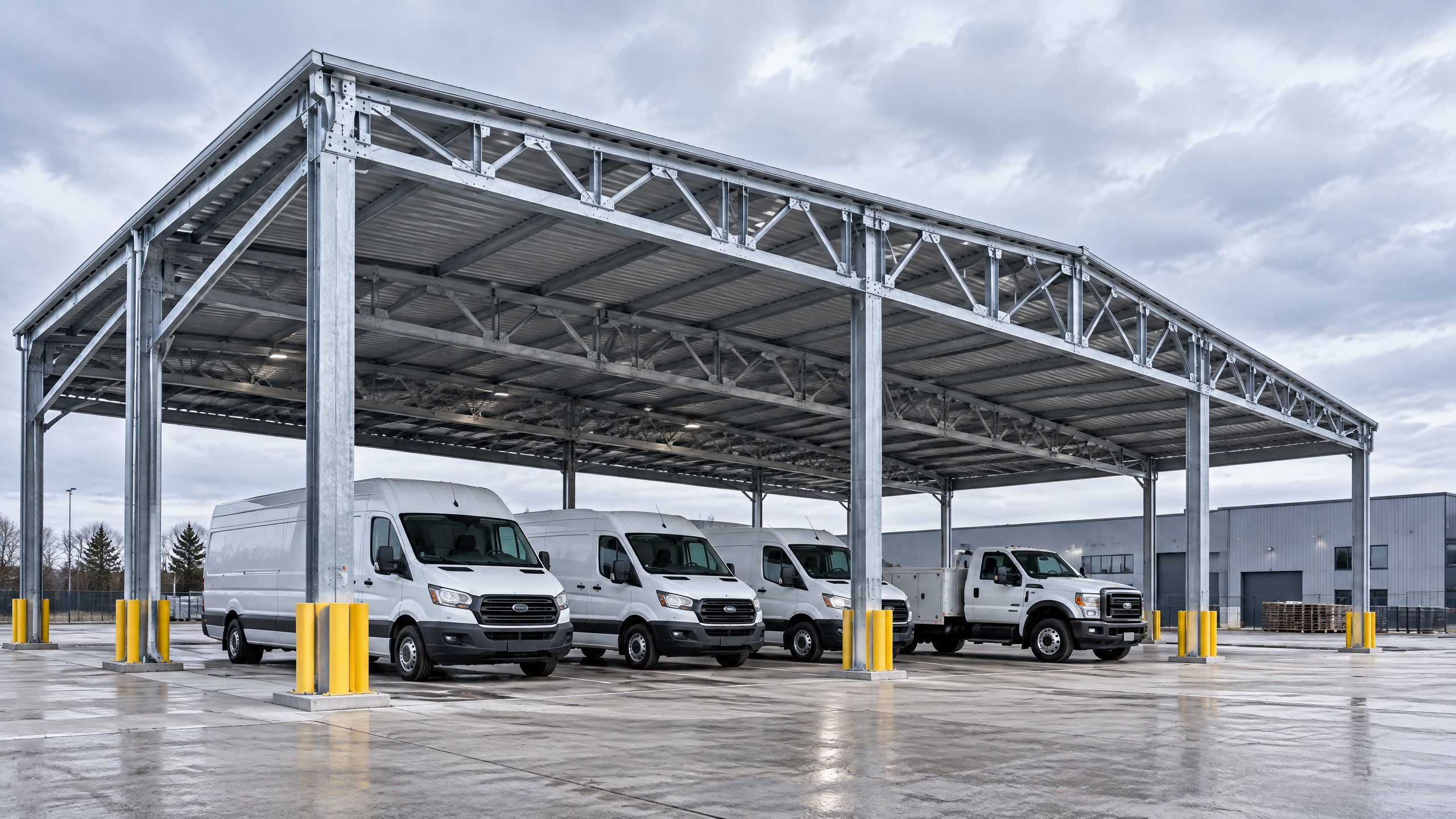
Industrial parking canopy steel structure matters when the project’s functional, structural and long‑term operational requirements exceed the capabilities, cost profile or delivery constraints of lighter‑gauge aluminium systems. Deciding whether to specify a steel canopy is a technical procurement choice driven by span and loading demands, integration with heavy logistics, attachment of heavy equipment (for example large PV arrays or HVAC), extreme environmental exposures, and required service life with specific maintenance regimes. For B2B buyers — distributors, architects, contractors, developers, solar EPCs and fleet operators — the decision must be made against an explicit project brief that documents loads, clearances, utility interfaces, local code limits and life‑cycle cost expectations. This guide explains when industrial parking canopy steel structure becomes the right option, what planning inputs and supplier evidence to require, how to coordinate on‑site operations and installation, and a practical six‑step buyer workflow to move from need to commission while managing implementation risk.
Buyer context and scope boundary: commercial and industrial applications
Audience and scope
- Intended readers: B2B buyers such as distributors, architects, contractors, developers, solar EPCs and fleet operators evaluating canopy options for commercial and industrial applications.
- Scope: decision criteria and procurement guidance where the primary structural element under consideration is an industrial parking canopy steel structure. The guide covers project planning inputs, technical interfaces, procurement evidence, on‑site installation and operational coordination—emphasising the differences between industrial/warehouse/fleet applications and routine architectural carports.
Common commercial and industrial use cases where steel becomes relevant
- Large logistics yards, heavy vehicle maintenance shelters and fleet wash bays where overhead clearances and lateral impact resistance are critical.
- Multi‑bay canopies spanning large column‑free areas for rapid vehicle throughput or equipment mounting.
- Canopies intended to support large distributed loads such as PV arrays with heavy ballast or equipment rooms integrated on top.
- Sites with high wind, seismic exposure or corrosive environments where thicker sections, heavier connections or specialized corrosion protection systems may be required.
Scope boundary and what this guide does not cover
- This guide does not provide project‑specific engineering calculations, final structural designs or prescriptive installation sequences. Those require a documented project basis and input from local qualified professionals, installers, utilities and authorities.
- Carportiva supplies architectural aluminium carports, commercial solar carports and industrial/fleet vehicle shelters. The guidance here helps decide when to consider industrial parking canopy steel structure as the primary option and what supplier evidence and onsite coordination to expect. For standard aluminium systems and modular options see all systems and sourcing guides.
Important mandatory note
- Site‑specific structural capacity, foundations, permits, electrical design, approvals, lead time, price, energy yield and warranty require a documented project basis and review by relevant local qualified professionals, installers, utilities and authorities before procurement or installation decisions are final.
Core decision principle: when the industrial parking canopy steel structure becomes the right solution
The core decision principle is: select a steel canopy when required structural performance, durable service life in demanding environments, or heavy integration needs cannot be met economically or practically by alternative materials and assemblies.
Key performance drivers that push toward steel
- Span and load: required clear column‑free spans or high vertical loads (heavy snow, concentrated equipment loads) that exceed the feasible section modulus or connection capacity available in aluminium systems.
- Impact and abrasion: locations with routine contact by heavy vehicles or materials handling equipment where higher mass and capacity of steel improve resistance to damage and deformation.
- Integration of heavy services: when roof structures must support large PV arrays with heavy ballast, transformers, battery containers or substantial conduit and cable trays.
- Fire and heat exposure: when the specification requires fire performance, thermal mass or specific coating systems that are more commonly implemented on steel structures.
- Long life, repairability and alterability: situations where a longer in‑service life, ease of on‑site repairs and future changes (extensions, re‑use) are planned.
- Local fabrication and maintenance ecosystems: steel may be preferable where local supply chains and labour specialise in steel fabrication and maintenance.
When aluminium or lighter systems may still be preferable
- Architectural appearance where minimal section depth and slim profiles are essential.
- Weight‑sensitive retrofits where existing high‑strength but limited load capacity cannot accept heavier footings.
- Lower load small‑commercial canopies, typical parking lots, or where corrosion environments are mild and spans limited.
Decision threshold checklist (qualitative)
- Required clear span > design limits of available aluminium modules? Consider steel.
- Concentrated or dynamic loads (gantries, maintenance equipment) anticipated? Consider steel.
- Heavy PV or rooftop equipment to be attached? Consider steel after PV engineering.
- Frequent high impacts from large vehicles? Consider steel.
Use the developer/owner brief and this guide to turn those qualitative triggers into a documented project basis for engineering.
Planning inputs: what you must define before procurement
A robust procurement decision requires a documented project basis. The following inputs should be defined, validated and delivered to prospective suppliers as part of the tender pack.
Mandatory project inputs
- Project brief and intended use: describe vehicle mix (types, heights, gross vehicle mass), traffic patterns, peak hourly throughput, and operational hours.
- Commercial parking layout and vehicle clearance planning: approved parking geometry, access aisles, entry/exit radius, and minimum clearances for the tallest vehicles. Refer to local accessibility guidance as applicable (see [1]) and geometric design guidance for parking areas (see [4]).
- Structural loads and environmental parameters: dead loads, live loads, snow/wind/seismic design criteria (local code), plus potential temporary loads during maintenance or installation.
- Soil report and foundation constraints: geotechnical report identifying bearing capacity, groundwater level and any relevant contamination or variability.
- Utilities and electrical: locations of power service, proposed EV chargers, conduit routes and integration points for PV arrays, including anticipated energy yield constraints (for PV, energy yield must be verified by a PV engineer).
- Permitting baseline: zoning, fire access, local building approvals and any special permits.
- Site logistics plan: crane access, storage areas, deliveries, temporary works and traffic management.
- Operational access coordination: details identifying maintenance routes, emergency egress, and interface with loading docks or service roads.
- Project programme: required completion date, lead time tolerance and milestones for procurement, fabrication and installation.
- Maintenance and warranty expectations: desired warranty periods and maintenance regimes for coatings, galvanization and bolted connections.
Vehicle clearance planning and commercial parking layout
- Document the minimum vertical clearance envelope for all vehicle types that will routinely use the canopy; include an allowance for dynamic bounce and roof fixtures on vehicles.
- Overlay the clearance envelope onto the commercial parking layout to ensure column positions and canopies do not introduce conflicts with circulation or loading bays.
Regulatory and safety references
- Accessible parking and space marking — consult guidance from regulators such as the U.S. Access Board for minimum accessible parking dimensions where applicable [1].
- Flood risk and site elevation — consult flood maps and local floodplain regulations; flood risk may change foundation strategy and finish levels [2].
- Construction safety, lifting and scaffold operations — installation activities must follow construction safety standards appropriate for the location; in the U.S., see OSHA construction standards [3].
Deliverable package for suppliers
- Consolidated tender pack including drawings, load cases, soil report, survey, utilities plan, required finishes and performance criteria.
- A project phasing plan that identifies procurement milestones, factory inspection windows and installation readiness dates.
- A named contact for on‑site coordination and change control.
Technical specification and key interfaces: what to include in the structural canopy specification
A clear structural canopy specification is the decisive document that converts project inputs into measurable supplier obligations. The specification should define materials, connections, protective systems, utility penetrations and interface tolerances.
Elements to include in the structural canopy specification
- Primary material: grade of steel (e.g., structural S‑grade per local standards), acceptance criteria for chemistry and mechanical properties, and required mill certificates.
- Protective systems: specify corrosion protection (hot‑dip galvanizing to a specified minimum coating weight, duplex systems with primer and topcoat, or specialised coatings for chemical/coastal exposure) and maintenance cycles.
- Section properties and spans: required spans, column grid, section modulus or moment capacity minimums, and limiting deflection criteria under service loads.
- Connection types and detailing: bolted vs welded connections, bolt classes and torque requirements, welding procedures and NDT requirements.
- Foundation interfaces: design reactions at base plates, anchor bolt patterns and tolerances, grout and baseplate leveling expectations.
- Roof and drainage interfaces: slope requirements, gutter and downpipe routing, snow guards, debris management and access for maintenance.
- PV and services integration: mounting interface, load paths for panels and rails, cable tray supports, clear access to inverters, and maintenance clearances. Define who supplies PV attachment details and how they are validated against canopy structure.
- Tolerances and dimensional control: erection tolerances for column positions and top‑of‑steel elevation so on‑site installers and precast/structural concrete contractors have clear acceptance criteria.
- Fire and smoke interfaces: specify clearances around building egress and any fire service penetrations or expectations for non‑combustible finishes where required by code.
- Acoustic and lighting attachments: weight and vibration limits for suspended luminaires, and routes for cable containment.
Interfaces and coordination responsibilities
- Structural engineer of record vs supplier: clarify which party verifies interface reactions, who supplies anchor bolt designs, and who accepts as‑built deviations.
- Electrical scope split: specify whether PV mounting hardware, cable trays and conduits are within the canopy supplier’s scope or the electrical contractor’s responsibility.
- Civil / foundations: define who supplies anchor bolts and who sets them in concrete (often the civil contractor with drawings supplied by the canopy supplier).
- Operational access coordination: the contractor should coordinate access routes and temporary works with site management; include this in the specification.
Testing, inspection and acceptance criteria
- Mill certificates for steel and material test reports.
- Dimensional checks at factory acceptance testing and again on arrival.
- Weld procedure specifications (WPS) and welder qualification records as required.
- Bolted connection torque calibration and post‑installation checks.
- Protective coating inspection and thickness measurements.
Note: the structural canopy specification must be developed in collaboration with the project structural engineer and validated against local building codes. It should also define who will sign off on each interface discipline to reduce disputes during erection.
Procurement and factory evidence: what to require from suppliers
Buyers must require verifiable factory and quality evidence to demonstrate compliance with the structural canopy specification and to reduce site risk. The following procurement evidence checklist is aimed at B2B purchasers preparing a technical evaluation.
Decision table — when steel procurement evidence is essential vs desirable
| Evidence type | Essential for industrial steel canopy procurement | Desirable / project dependent |
|---|---|---|
| Mill certificates and material traceability | Yes | — |
| Welding Procedure Specifications (WPS) and welder qualifications | Yes | — |
| Galvanizing / coating certificates with thickness readings | Yes (for corrosive or coastal environments) | Desirable for mild environments |
| Shop drawings with connection detail and anchor bolt patterns | Yes | — |
| Factory Acceptance Test (FAT) / dimensional control reports | Yes | — |
| Non‑destructive testing (NDT) reports for critical welds | Yes (for load‑bearing or fatigue‑sensitive details) | Depending on code |
| Paint adhesion and thickness tests | Desirable | Yes for duplex systems |
| Production photos and shipment packing list | Desirable | Yes |
| Third‑party QA audit reports or ISO factory certifications | Desirable | Helpful for risk mitigation |
| Load test certificates for specially required components | Yes for custom lifting attachments | Optional for standard frames |
Factory acceptance and QA checklist (table)
| QA element | Purpose | Who verifies |
|---|---|---|
| Material traceability (MTR) | Confirms steel grade/strength | Buyer/Supplier QA |
| Dimensional inspection report | Ensures fabrication matches shop drawings | Buyer rep / third‑party inspector |
| Weld quality and WPS logs | Validates welding meets spec | Third‑party or buyer QA |
| Protective coating inspection | Verifies coating system and thickness | Coating inspector or third‑party |
| Bolted connection torque specifications | Confirms bolting performance | Supplier & site erector |
| Protective packing and sea/land transport prep | Prevents damage during transit | Supplier & logistics |
What to include in tender evaluation criteria
- Technical compliance: pass/fail on structural canopy specification items.
- Factory quality evidence: MTRs, WPS, NDT and FAT completion.
- Installation readiness: evidence of installation methodologies, lift plans and temporary works coordination.
- Lead time and supply chain transparency: detailed schedule showing key milestones.
- After‑sales and warranty: clarity on scope and exclusions; do not accept vague statements—require written warranty clauses tied to measurable defects.
Avoiding common procurement pitfalls
- Accepting “equivalent” without verification: require documented evidence and allow time for technical clarifications.
- Not defining acceptance tolerances: ambiguous tolerances create disputes on site.
- Mixing civil and structural responsibilities: clearly split responsibilities for anchor bolt supply and setting, foundation tolerances, grout and backfill.
- Assuming factory QA replaces site inspection: both are necessary; specify when buyer or third‑party inspections will occur.
Site installation, logistics and operations: coordinating the build and handover
Installation readiness and on‑site coordination are where procurement decisions meet reality. Effective planning reduces change orders, delays and safety incidents.
Site and logistics checklist before mobilisation
- Installation readiness: confirm the site is cleared, surfacing completed where required, and temporary facilities (welfare, power) are in place.
- Foundation availability: confirm foundations and anchor bolts are set to the supplier’s tolerances; if anchor bolts are by the supplier, verify placement drawings and embedment details.
- Crane and lifting plan: define crane pick points, crane pad capacity and lift radii; include all necessary tertiary lifting equipment.
- Access and storage: allocate secure, level storage areas near installation points to minimise handling.
- Temporary traffic management: ensure separation between installation zones and active circulation for vehicles and pedestrians.
- Safety plan: verification of site safety documentation and compliance with local construction safety regulations (e.g., OSHA standards in jurisdictions where applicable) [3].
- Environmental constraints: dust, noise and working hours per local regulations and community agreements.
Installation phasing and project phasing plan
- Issue a project phasing plan that sequences deliveries and installation to avoid double handling and minimizes interface conflicts with other trades.
- Example phasing: site survey → foundations → delivery of columns → erection of primary beams → installation of secondary members and roof deck → PV/electrical works → commissioning.
- Coordinate PV work so that structural and electrical interfaces are clearly scheduled, avoiding premature sealing of access points needed by electrical contractors.
Operational access coordination
- Define routes for maintenance vehicles and emergency services; make sure columns and bracing do not impede service paths.
- Ensure clearances for lifts, cranes or maintenance platforms used for rooftop equipment inspection.
- Provide a documented maintenance access plan to facility managers when handing over.
Testing, commissioning and acceptance
- Commissioning should verify structural fixity, correct torque of bolted connections, drainage performance, PV mounting integrity and electrical isolation.
- Document a snag list and rectify items before final acceptance. Record as‑built drawings and maintenance manuals for ongoing operations.
- Where PV is installed, confirm electrical commissioning and energy yield modelling with the PV contractor; energy yield and PV performance require separate engineering verification and are not the responsibility of structural suppliers unless explicitly stated.
Safety and construction standards
- Installation and temporary works must adhere to local construction safety codes. In the U.S., OSHA construction standards provide requirements for fall protection, crane operations and scaffolding [3]. Equivalent national regulations apply elsewhere — consult local authorities.
Flooding and elevation considerations
- If the site is in a floodplain, the elevation of electrical equipment, foundations and access routes must reflect flood maps and design guidance [2]. Flood risk may change both foundation design and the choice of materials/coatings.
Mid‑article call to action For project enquiries, technical clarification or to discuss Titan industrial and logistics system integration, contact our team via /inquiry or info@carportiva.com.
Implementation risks and mitigation: common failure modes and controls
Understanding risk typologies and explicit mitigations helps avoid costly rework.
Top implementation risks
- Mis‑specified loads and clearances
- Risk: Column positions or roof elevations conflict with vehicle clearance envelopes or loading equipment.
- Mitigation: Validate commercial parking layout and vehicle clearance planning early; require vendor confirmation of column locations against the client’s layout.
- Foundation misalignment or inadequate capacity
- Risk: Anchor bolts set out of tolerance, or foundations failing to meet bearing pressure, causing delays or rework.
- Mitigation: Issue coordinated setting drawings; require geotechnical report and early verification of anchor setting by third‑party survey.
- Interface disputes between trades
- Risk: Electrical or PV contractors and structural suppliers have conflicting assumptions about fixing points or cable routes.
- Mitigation: Clarify scope split in procurement documents and run cross‑discipline workshops during design development.
- Corrosion and environment mismatch
- Risk: Inadequate protective systems for coastal/chemical exposures lead to premature failure.
- Mitigation: Specify appropriate protective systems and maintenance cycles; consider duplex systems and maintenance plans.
- Supply chain and lead time shocks
- Risk: Long lead times for bespoke steel sections create programme risk.
- Mitigation: Early procurement, require detailed supplier schedules and contingency options; consider modular designs where feasible.
- Installation site safety failures
- Risk: Incidents during lifting or erection due to inadequate lifting plans or uncertified rigging.
- Mitigation: Require certified rigging plans, qualified riggers, and adherence to local safety standards (e.g., OSHA where applicable) [3].
- Warranty and performance disputes
- Risk: Vague warranty terms or exclusions for coatings, galvanizing or attachments.
- Mitigation: Require clear warranty clauses and define accredited failure modes; tie warranty to measurable maintenance actions.
Risk management controls (table)
| Risk | Early control | On‑site control | Contractual control |
|---|---|---|---|
| Mis‑specified clearances | Include clearance envelopes in tender pack | Pre‑erection survey and layout checks | Acceptance tolerances and as‑built sign‑off |
| Anchor bolt/foundation errors | Provide coordinated anchor drawings | Third‑party survey of anchors before erection | Holdbacks or rectification clauses |
| Corrosion in hostile environments | Specify coatings and lifecycle | Coating inspection and maintenance schedule | Warranty terms tied to maintenance |
| Interface disputes | Cross‑discipline coordination meetings | Site coordination manager | Scope split clarified in contract |
| Lead time delays | Early procurement and schedule review | Phased delivery | Liquidated damages or schedule milestones |
Legal and contractual notes
- Contracts should define responsibility for latent defects, supply chain substitutions, and how variations are priced and approved. Large industrial canopies typically require clearly defined variations processes.
A named six‑step buyer workflow: The Carportiva Industrial Canopy Procurement Pathway
This workflow is engineered for B2B buyers procuring an industrial parking canopy steel structure. Each step lists primary actions, deliverables and decision gates.
Step 1 — Define: Project brief and constraints
- Actions: Create detailed project brief (use cases, vehicle types, commercial parking layout, clearance envelopes, site plan, utilities).
- Deliverables: Documented project basis with vehicle clearance planning, geotechnical report request, budget range and schedule.
- Decision gate: Proceed when the brief is complete and validated by the project team.
Step 2 — Survey & feasibility
- Actions: Conduct site survey, geotechnical investigation, flood risk check and utility verification.
- Deliverables: Site survey report, soil report, identified constraints and preliminary load cases.
- Decision gate: Go/no‑go on steel option versus alternatives based on span and load feasibility.
Step 3 — Specify & tender
- Actions: Produce a structural canopy specification and tender pack, include project phasing plan and installation readiness dates, and invite suppliers to tender.
- Deliverables: Tender documents, supplier Q&A, and pre‑qualified supplier list.
- Decision gate: Award based on technical compliance, factory evidence and commercial terms.
Step 4 — Detailed design & factory QA
- Actions: Supplier produces shop drawings, material lists and factory QA plan. Arrange FAT and third‑party inspections as required.
- Deliverables: Approved shop drawings, MTRs, WPS, NDT reports and coating certificates.
- Decision gate: Release to fabrication after approval of drawings and QA plan.
Step 5 — Logistics & installation
- Actions: Coordinate deliveries, confirm foundations and anchor bolts, implement site safety plan and execute erection sequence per installation readiness plan.
- Deliverables: Installation phase schedule, crane plans, lift plans, site safety records and interim inspections.
- Decision gate: Commissioning can proceed when all QA checks and structural inspections are complete.
Step 6 — Commissioning & handover
- Actions: Conduct final inspections, testing (including PV/electrical if applicable), provide as‑built drawings and maintenance manuals.
- Deliverables: Handover pack, warranties, maintenance schedule, and final acceptance certificate.
- Decision gate: Final acceptance and start of warranty period upon completion of rectifications.
This six‑step pathway is iterative; changes in scope should loop back to appropriate earlier steps and trigger design re‑validation.
Frequently asked questions (FAQ)
Q: When is industrial parking canopy steel structure essential rather than optional? A: It becomes essential when required spans, concentrated loads, impact resistance or heavy equipment attachments make lighter systems structurally impractical or uneconomic. Use the documented project basis to quantify loads and evaluate alternatives.
Q: How do I reconcile vehicle clearance planning with column positions? A: Define the full vehicle envelope with allowances, overlay it on your commercial parking layout and make column placement an explicitly validated part of the tender pack. Require vendor confirmation and a pre‑erection template check.
Q: Can steel canopies support large PV arrays? A: Yes, but PV mounting loads, wind uplift and service access must be engineered into the structural canopy specification. The PV engineer must verify energy yield and attachment loading; energy yield is a separate deliverable from PV specialists.
Q: What protective systems are commonly used for steel in coastal sites? A: Duplex systems (hot‑dip galvanizing plus a high‑performance paint) or specialised coatings are often used. Specify coating performance and inspection regimes; local corrosivity class should be considered. Do not omit maintenance obligations from tender documents.
Q: Who is responsible for anchor bolts and setting them? A: Responsibility should be defined in the contract. Typical splits: structural supplier supplies anchor bolt drawings and embedded items; civil contractor sets anchors per suppliers’ templates. Clarify on the tender pack and confirm prior to concrete pour.
Q: How do I manage lead time risk? A: Early procurement decisions, defined project phasing plan, and staged deliveries mitigate risk. Require supplier schedules and critical path milestones in the procurement terms.
Q: What inspections should I plan during installation? A: Dimensional checks, weld inspection/NDT where required, coating thickness readings, bolt torque verification, and final load path checks. Include third‑party inspections if required by risk profile.
Q: Do building codes or accessibility standards matter for canopies? A: Yes. Accessibility dimensions for parking should be referenced from applicable guidance such as the U.S. Access Board where applicable [1]. Local building codes determine snow/wind/seismic loads and must be followed.
Q: Who signs off on final structural acceptance? A: Usually the project structural engineer of record, the supplier QA inspector and the client’s representative jointly document final acceptance. Define acceptance criteria and sign‑off roles contractually.
Conclusion: make industrial parking canopy steel structure a measured procurement choice
Selecting an industrial parking canopy steel structure is a technical, programme and lifecycle choice that should be made against a documented project basis. Use the core decision principle — match material and detail to structural demand, environmental exposure and operational integration — to guide whether steel is required. Build a tender pack that includes clear commercial parking layout and vehicle clearance planning, a comprehensive structural canopy specification, a project phasing plan, factory QA evidence requirements and installation readiness criteria. Use the six‑step buyer workflow to structure procurement and maintain tight control over interfaces and risks.
Remember: site‑specific structural capacity, foundations, permits, electrical design, approvals, lead time, price, energy yield and warranty require a documented project basis and review by relevant local qualified professionals, installers, utilities and authorities before final procurement decisions or construction.
For technical discussions about integrating shore‑based logistics or heavy duty fleet shelters with standard systems, or to discuss the Titan industrial and logistics system, our team can help. For broader options see all systems and consult our sourcing guides. To discuss a specific project, contact us via /inquiry or info@carportiva.com.
References (selected)
- U.S. Access Board — parking guidance for accessible parking dimensions and layout [1].
- FEMA — flood maps and floodplain considerations relevant to foundation and elevation planning [2].
- OSHA — construction standards applicable to installation, lifting and site safety [3].
- Federal Highway Administration — guidance on parking area geometry and design considerations [4].
References
- U.S. Access Board parking guidance: https://www.access-board.gov/ada/guides/chapter-5-parking/
- FEMA flood maps: https://www.fema.gov/flood-maps
- OSHA construction standards: https://www.osha.gov/laws-regs/regulations/standardnumber/1926
- Federal Highway Administration: https://highways.dot.gov/
Keep the project brief connected.
Bring the actual project brief to the engineering table.
Share your location, layout, target application and available technical inputs. Carportiva can help identify the relevant product-interface information before a project-specific commercial discussion.
Request a project discussion