Direct answer (120–180 words)
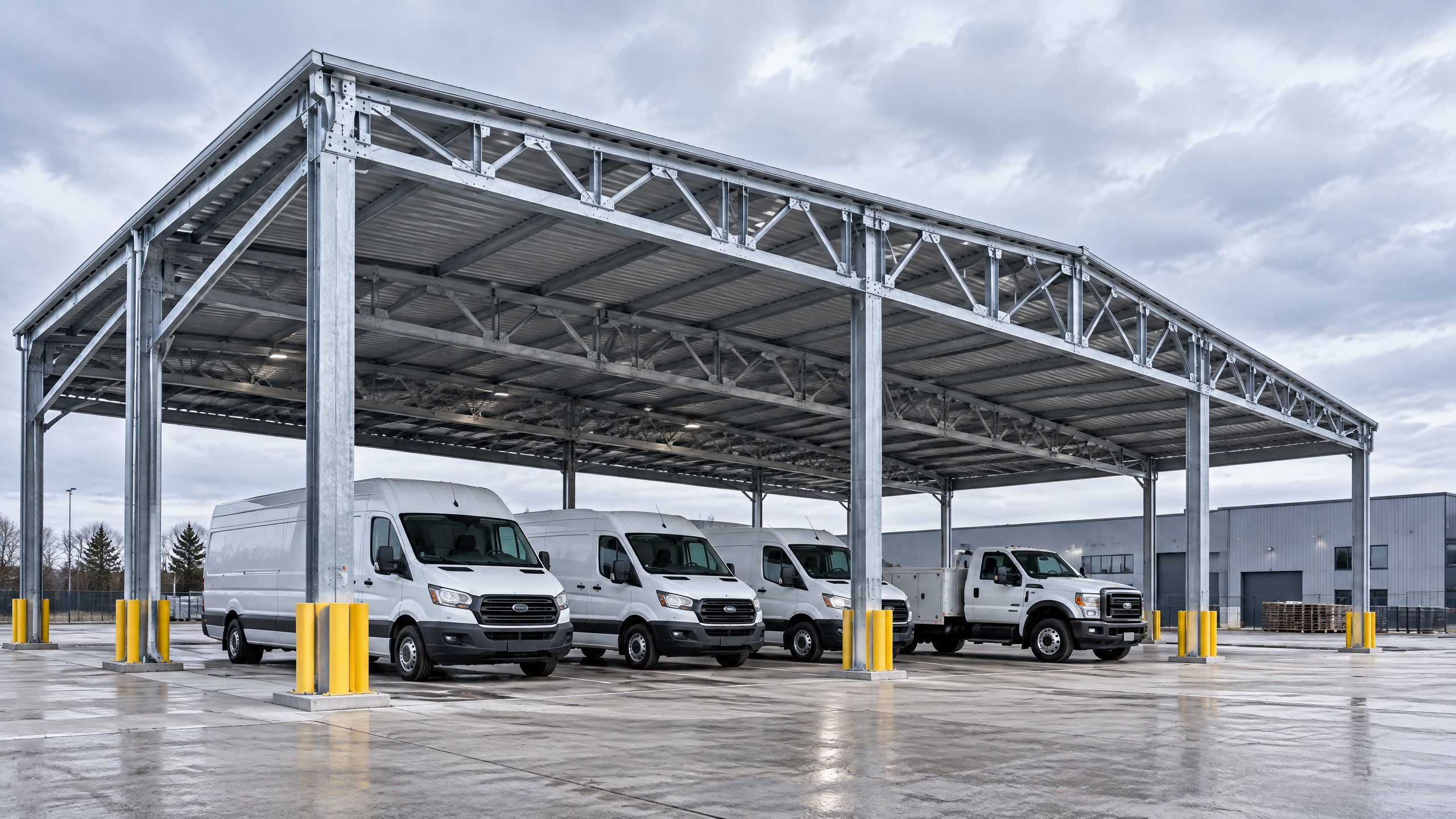
Specifying logistics yard carport vehicle clearance is a design-led procurement decision: start with the operational vehicle types and their dynamic swept paths, then set clear vertical and horizontal envelopes (including canopy overhangs, column offsets, and approach/egress aisles) that preserve safe, efficient movement and loading operations. Capture those envelopes in the commercial parking layout, coordinate them with utilities, drainage and services, and lock them into the structural canopy specification. Require manufacturer-supplied structural calculations, fabrication drawings and factory evidence tied to a documented project basis. Integrate vehicle clearance planning into the project phasing plan and installation readiness checks so foundations, permits and siteworks are complete before canopy delivery. Finally, verify compliance, collision protection and contractor competency through staged approvals, FAT-style inspections and an operational access coordination protocol with site operators. Site-specific structural capacity, foundations, permits, electrical design, approvals, lead time, price, energy yield and warranty all require a documented project basis and engagement of local qualified professionals, installers, utilities and authorities.
Buyer context and scope boundary: why logistics yard carport vehicle clearance matters
A logistics yard carport is not a decorative roof — it’s an engineered element in a high-movement operational environment. When the primary objective is to protect vehicles, cargo handling and site staff while preserving throughput, clearance decisions determine safety, capacity and future adaptability.
Scope boundary for this guide
- Primary subject: logistics yard carport vehicle clearance — vertical and horizontal envelopes around canopies and their interfaces with moving vehicles, equipment and site structures.
- Applications covered: commercial and industrial yards, fleet parking, loading/unloading canopies, solar carport arrays in logistics contexts.
- Not covered in technical depth: local statutory permitting processes, geotechnical investigations and electrical distribution design — these must be defined per project by local professionals.
Who should use this guide: distributors, architects, contractors, developers, solar EPCs and fleet operators buying carport systems (including architectural aluminium carports and industrial/fleet shelters). Use the guide to convert operational requirements into procurement-ready specifications and acceptance criteria.
Key deliverables you should generate from this phase
- A vehicle fleet matrix (vehicle types, heights, widths, swept path templates)
- Commercial parking layout with clearances, column grid and service routing
- Structural canopy specification with column capacities and offsets
- Project phasing plan and installation readiness checklist
- Sourced procurement package including factory evidence and QA acceptance criteria
Core decision principle: align clearance envelopes with operational throughput
The single principle that steers all subsequent decisions is alignment: clearance envelopes must be set to accommodate the largest vehicle and movement pattern that will reasonably operate under the canopy, plus a safety margin for driver error, loading equipment and potential future fleet mix changes.
Translate alignment into measurable decisions:
- Define the controlling vehicle (not the mean or most frequent vehicle).
- Capture both static clearance (parked vehicles, rooftop loads) and dynamic clearance (swept path while turning, tail swing).
- Add a minimum operational buffer (usually project-specific; document the rationale).
- Reflect that buffer consistently across canopy plan, column locations, drainage and pedestrian routes.
Operational examples (illustrative): a site with regular heavy rigid trucks will typically require higher vertical clearance and wider approach aisles than a site serving vans and pick-ups. Where forklifts or side-loaders operate beneath canopies, horizontal clearance and column protection must support lateral movements.
Planning inputs: what you must collect before specifying clearances
Before writing the procurement specification, collect these inputs. They form the documented project basis that suppliers, engineers and authorities will rely on.
- Vehicle fleet matrix (required)
- Vehicle make/model or type
- Static height and roof fittings (antennas, lights)
- Max loaded height, including pallets or stacked items
- Width, wheelbase and rear overhang/tail swing
- Typical turning radius and articulated articulation if applicable
- Operational scenarios
- Normal parking, loading/unloading, staging
- Manoeuvre patterns (forward-in, reverse out; drive-through)
- Equipment operating under canopy (mobile cranes, forklifts)
- Pedestrian and bicycle routes adjacent to canopies
- Site constraints and geometry
- Existing structures, kerb lines, drainage channels, utilities
- Ground gradients and elevation changes
- Flood risk zones (consult FEMA maps or equivalent) [2]
- Access rights and road hierarchy
- Regulatory and safety inputs
- Local parking and accessibility guidelines (ADA/Access Board where applicable) [1]
- Construction safety and temporary works standards (OSHA guidance where applicable) [3]
- Highway/road interface requirements if the canopy abuts public carriageways [4]
- Structural and geotechnical baseline
- Soil bearing capacity and available foundation types
- Existing or proposed pavement sections and loading capacities
- Performance drivers
- If solar integration is required: module tilt, row spacing and inverter/electrical access
- Desired guttering and drainage detail to avoid ponding
- Desired warranty, maintenance intervals and access needs
Documenting these inputs into a single “clearance basis” report reduces ambiguity and is essential for later evidence, approvals and contractual acceptance.
Technical specification and interfaces: turning inputs into measurable requirements
Translate operational inputs into a technical specification that suppliers and engineers can price and validate. The specification must contain measurable parameters, acceptance methods and interface responsibilities.
Key specification elements
- Clearance envelopes (explicit)
- Vertical clearance: maximum required height under all canopy elements (including lighting, gutters and service ducts). State point locations (e.g., along drive aisles, over loading banks).
- Horizontal clearance: carriageway width between structural obstructions; column offsets from kerbs and dock edges.
- Overhangs and eave lines: maximum permitted projection beyond columns into manoeuvre areas.
- Column grid and setback requirements
- Column spacing and offsets relative to parking bays and traffic lanes.
- Column dimensions, protective zones and recommended collision protection devices.
- Structural canopy specification
- Material system (e.g., aluminium framing, bolted connections).
- Design load cases required (dead, live, wind, snow, maintenance loads) — request that suppliers include basis of design and reference local codes.
- Connection details for foundations and services (embed plate locations, conduit sleeves).
- Interfaces with services
- Electrical raceways, PV cable routes if solar installed, lighting mounting and maintenance access.
- Drainage outlet locations and scupper positions aligned to site drainage.
- Fire service and vehicle access egress requirements.
- Dynamic movement interfaces
- Swept path templates or CAD overlays showing turning manoeuvres under the canopy.
- Speed limits, signage and traffic calming measures to limit collision risk.
- Installation and maintenance access
- Access for cranes, lifting equipment and man-lifts during both construction and later maintenance.
- Safe walkway clearance for personnel beneath canopies; anti-slip finish and edge protection as applicable.
Decision table: typical clearance targets (illustrative guidance — confirm for project)
| Use case / Controlling vehicle | Typical minimum vertical clearance | Typical minimum aisle width (one-way) |
|---|---|---|
| Vans and passenger vehicles | 2.6–3.0 m | 3.0–3.5 m |
| Light commercial vehicles (sprinter-type) | 3.0–3.5 m | 3.5–4.0 m |
| Rigid trucks and small HGVs | 3.5–4.5 m | 4.5–6.0 m |
| Articulated trucks / container reach | 4.5–5.5 m+ | 6.0–8.0 m+ |
Note: the table provides common design ranges; the controlling vehicle must determine your project-specific targets.
Interfaces and allocation of responsibility table
| Interface | Typical allocation (buyer vs supplier) | Evidence required at tender |
|---|---|---|
| Foundation capacity and geotech | Buyer | Geotechnical report, founding level, allowable bearing |
| Column connection plate / embed positions | Supplier provides details, buyer approves | Foundation layout drawing with anchor bolt locations |
| Electrical routing for PV/lighting | Buyer defines network points; supplier details raceways | Single-line diagrams, conduit sizes |
| Roadway markings and traffic management | Buyer | Traffic management plan, phasing plan |
| Structural design for wind/snow | Supplier to design per local code; buyer to confirm code basis | Structural calculations and load cases stamped by engineer |
Always specify who approves each interface deliverable and require documented sign-off before factory fabrication or foundation dig.
Procurement and factory evidence: what to require and how to verify it
Procurement decisions must be evidence-led. The buyer needs assurance that the chosen system will meet the clearance and structural specification once installed. Set minimum documentary evidence requirements in the contract and tender evaluation.
Minimum procurement evidence checklist (require at tender)
- Project-specific fabrication drawings showing column locations, canopy extents, overhangs and service penetrations.
- Structural calculations referencing the project basis of wind, snow and dead loads and confirming deflections that affect clearance.
- Material traceability (mill certificates for primary metals).
- Surface finish and corrosion protection specification.
- Welding and jointing procedures where applicable.
- Assembly drawings and a factory acceptance checklist showing critical dimensions that affect clearance envelopes.
- Installation method statement and lifting plan.
- QA inspection reports and non-conformance process.
Factory verification practice
- Require dimension checks on primary elements (e.g., beam lengths, ridge heights) and photographic evidence with a scale reference.
- For critical vertical clearance-sensitive projects, request a pre-shipment dimensional mock-up or a “dry-fit” check of key members to verify datum heights.
- Ask for evidence of quality control for bolt tensioning and pre-fabricated connection interfaces.
Tender evaluation weighting Include clearance-related items in the technical weighting. Examples:
- Conformity of fabrication drawings to the clearance basis (20%)
- Structural calculations and stamped design (20%)
- Factory QA and dimensional evidence (15%)
- Lead time and delivery sequencing aligned to the project phasing plan (15%)
- Installer competency and references (30%)
Do not accept generic data sheets only. Insist on project-specific documents and a documented project basis; otherwise acceptance testing at site will be difficult.
Site installation and operations: making clearance real on site
Once procurement is settled, focus on making the theoretical clearance reality on site. Installation is where small tolerances become operational constraints.
Installation readiness (explicit checks)
- Foundations: excavation, reinforcement and anchor positions completed and verified against the supplier’s foundation layout.
- Datum levels: established with survey control and communicated to supplier. Datum errors are a primary cause of clearance non-conformances.
- Utilities: sleeves and conduits installed to plan; no unmarked services encroaching into column zones.
- Temporary works: staging areas and crane positions planned so they do not reduce approach widths during critical lifts.
- Traffic management: operational access coordination plan implemented to segregate construction traffic from ongoing logistics.
Operational access coordination
- Produce an operational access coordination protocol that defines vehicle routing during works, timing windows for deliveries and protective measures (barricades, signage).
- Include the site operations team and drivers in a pre-works briefing to ensure they understand temporary changes and final canopy clearances.
Commissioning checks for clearance acceptance
- Verify vertical clearance at all marked control points using calibrated levelling instruments. Record photographic and measured evidence.
- Perform a dynamic test: guide a representative vehicle through the critical maneuvers with driver and safety personnel; log any near-miss or restriction.
- Confirm all finish elements (lighting housings, gutters, PV racking) are within tolerance and won’t reduce clearance over time (e.g., sagging gutter lines).
Operational tips for ongoing safety
- Apply visible kerb or column protection and high-visibility markings for columns within manoeuvre zones.
- Use collision detection or physical speed reducers in high-risk approach lanes.
- Maintain a documented log of any changes in fleet that could affect clearance (new roof-mounted equipment, taller vehicles).
Implementation risks and mitigations: common failures and how to avoid them
Understanding common implementation risks reduces schedule slippage and cost overruns. Below are prevalent risks with practical mitigations.
Risk: Unclear controlling vehicle leading to undersized clearance
- Mitigation: Formalise vehicle fleet matrix as a contractual datum. Make the supplier’s structural bidding documents reference that datum.
Risk: Datum and foundation location errors causing vertical misfits
- Mitigation: Require survey verification and anchor bolt templates before fabrication. Use a pre-installation “hold point” to check anchor positions.
Risk: Service clashes (electrical conduits, drainage) reducing clearance
- Mitigation: Early coordination meeting with utilities, supplier and site civils. Lock service locations in the project phasing plan.
Risk: Supplier-produced components outside tolerance
- Mitigation: Request factory dimensional reports and an on-site or off-site dry-run of major assemblies. Specify remedies and rework responsibilities in contract.
Risk: Temporary works reducing operational throughput during installation
- Mitigation: Staged installation plan that preserves critical access lanes during peak operational periods and embeds operational access coordination.
Risk: Environmental exposure (flooding, high wind) affecting clearance and structural performance
- Mitigation: Consult flood maps (FEMA or local equivalent) early [2]. Require supplier to state design code basis and local authority approvals.
Risk: Safety non-conformance during construction
- Mitigation: Enforce construction safety standards (OSHA guidance for construction operations where applicable) and require contractor method statements [3].
Record all non-conformances and agreed remedial actions in a formal snag list with responsible parties and target completion dates. This is essential for handover and warranty triggers.
A named six-step buyer workflow: specify — procure — install — verify — handover — operate
This practical, named workflow converts the guidance into a repeatable procurement process.
- Specify — Define the clearance basis
- Create the vehicle fleet matrix and commercial parking layout.
- Document controlling vehicle, tolerance margins and interface responsibilities.
- Produce a preliminary structural canopy specification.
- Procure — Tender with evidence requirements
- Issue tender documents requiring project-specific fabrication drawings, structural calculations and factory QA evidence.
- Evaluate based on technical conformity, installation readiness and references.
- Prepare — Site readiness and phasing
- Complete foundations, datum surveys and services.
- Implement a project phasing plan aligned to operations and deliveries.
- Install — Controlled erection and verification
- Conduct pre-lift checks, set hold points and confirm anchor location.
- Check vertical/horizontal clearances at marked control points during erection.
- Verify and handover — Acceptance testing
- Run dynamic vehicle tests and document clearance acceptance.
- Handover with an operations manual, as-built drawings and maintenance plan.
- Operate — Monitoring and change control
- Log any fleet changes and perform periodic visual clearance audits.
- Maintain a process for rapid intervention if new equipment encroaches on clearances.
Each step must produce tangible documents or acceptance records to avoid disputes later. Embed contractual hold points at transitions between steps 2→3 and 4→5.
Frequently asked questions (FAQ)
Q: How do I determine the controlling vehicle for clearance? A: The controlling vehicle is the largest vehicle expected to operate regularly under the canopy or during peak operations. Capture its static height and loaded height (including cargo and roof fittings). Where multiple vehicle types operate, choose the tallest or longest vehicle based on risk and throughput, and document the operational frequency.
Q: Are design clearance ranges universal? A: No. Clearance ranges differ by region, operational need and vehicle fleet. The table earlier gives common guidance, but you must confirm the project-specific targets and local code requirements.
Q: What margin should I add for driver error? A: Margin is project-specific. Many projects define a safety buffer of 0.2–0.5 m vertically for roof fittings and an equivalent lateral buffer, but select a margin after observing site operations and consulted driver behaviour. Record the rationale.
Q: Who is responsible for conflicts with existing utilities? A: Typically, the buyer must provide verified utility locations and install required sleeves. The supplier should design column positions to avoid confirmed utilities; contractual allocation should be explicit (see the procurement allocation table).
Q: What evidence should I require to accept canopy delivery? A: At minimum: project-specific drawings, stamped structural calculations referencing your project basis, factory dimensional verification, and installation method statements. Require site verification of foundations and datum levels before installation.
Q: How do PV modules affect vehicle clearance? A: PV modules and racking can increase canopy thickness, reduce vertical clearance or create maintenance access requirements. Incorporate module and inverter positions into the clearance basis and confirm with your solar EPC. See Titan industrial and logistics system for integrated system information.
Q: Should I plan for future fleet changes? A: Yes. Include a change-control process and consider designing columns with the option to relocate or extend in future. Document potential future vehicle types and their effect on clearances in your project phasing plan.
Q: Where can I find guidance on accessible parking clearances? A: Use the U.S. Access Board guidance for parking where applicable; it provides useful layout and access details [1].
Implementation checklist (pre-tender to handover)
- Vehicle fleet matrix finalised and signed off
- Commercial parking layout with column positions issued
- Structural canopy specification published and referenced in tender
- Procurement requires project-specific fabrication drawings and calculations
- Foundations and services installed to supplier templates
- Datum verified and anchor positions checked
- Installation readiness checks completed (crane, traffic management, protective works)
- Dynamic vehicle clearance test completed and recorded
- Handover pack with as-built drawings, maintenance instructions and warranties delivered
Remember: site-specific structural capacity, foundations, permits, electrical design, approvals, lead time, price, energy yield and warranty require a documented project basis and relevant local qualified professionals, installers, utilities and authorities.
Conclusion and next steps
Specifying logistics yard carport vehicle clearance is an integrative activity: start from operations, convert to measurable design targets, demand project-specific procurement evidence, and manage installation with tight coordination between site teams and suppliers. Clear contractual allocation of responsibilities, coupled with a documented project basis and installation readiness checks, reduces risk and preserves operational throughput.
If you need system-level starting points or want to review product compatibility with your clearance basis, explore all systems and our sourcing guides. For detailed information on integrated industrial solutions, see the Titan industrial and logistics system.
Mid-article next step: to discuss a specific clearance basis or request a project review, open an inquiry /inquiry or contact our technical team at info@carportiva.com.
Appendix: example procurement document table (use in tender pack)
| Document required | Purpose | Acceptance check |
|---|---|---|
| Project-specific fabrication drawings | Ensure dimensions conform to clearance basis | Signed and dated drawings with tolerances |
| Structural calculations | Confirm canopy meets load cases without excessive deflection | Engineer-stamped calculations referencing local codes |
| Factory dimensional verification | Verify that critical members meet length/height tolerances | Photos and measurement table with calibration info |
| Installation method statement | Demonstrate safe erection and protection of clearances | Approved method statement with traffic management |
| As-built drawings & maintenance manual | Post-installation reference for operations | Handover pack at practical completion |
Closing CTA: For a project-specific quotation, technical clarification or to arrange a site readiness review, open an inquiry /inquiry or email info@carportiva.com.
External guidance references (selective)
- Parking and accessible guidance: U.S. Access Board (parking guidance) [1]
- Flood risk mapping: FEMA flood maps [2]
- Construction safety standards: OSHA construction standards [3]
- Roadway and truck interface considerations: Federal Highway Administration guidance [4]
Note: This guide provides procurement and engineering practice guidance. It does not substitute for project-specific structural design, geotechnical investigation, electrical design, permits or local authority approvals; those must be provided by qualified local professionals.
References
- U.S. Access Board parking guidance: https://www.access-board.gov/ada/guides/chapter-5-parking/
- FEMA flood maps: https://www.fema.gov/flood-maps
- OSHA construction standards: https://www.osha.gov/laws-regs/regulations/standardnumber/1926
- Federal Highway Administration: https://highways.dot.gov/
Keep the project brief connected.
Bring the actual project brief to the engineering table.
Share your location, layout, target application and available technical inputs. Carportiva can help identify the relevant product-interface information before a project-specific commercial discussion.
Request a project discussion