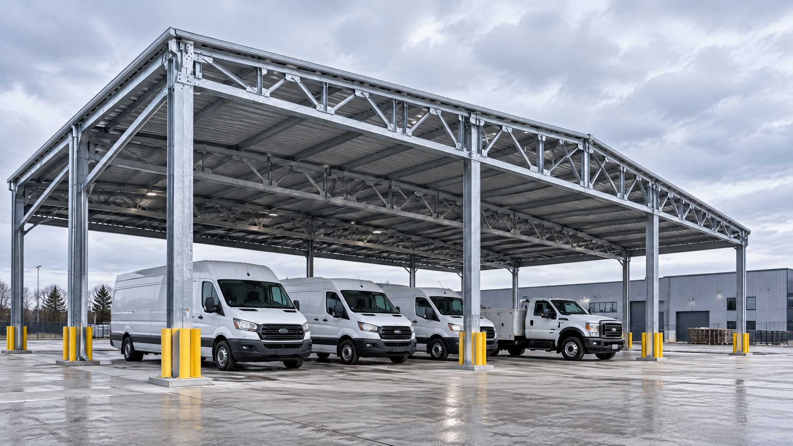
Direct answer (120–180 words) Evaluating public transport shelter canopy installation planning requires treating the canopy as a multi-disciplinary, project-managed asset rather than a single-line purchase. Buyers should align scope, stakeholders and decision gates up front: clarify the service envelope (shelter footprint, passenger flow, solar or non-solar canopy, electrical and lighting), obtain site surveys (topography, utilities, geotechnical and flood risk), and define clear technical criteria such as structural canopy specification, commercial parking layout impacts and vehicle clearance planning. Procurement must demand factory evidence (material traceability, finish QA, welding/procedure documentation), and the project plan must include operational access coordination, an explicit project phasing plan and installation readiness checkpoints. All final design and approvals for foundations, electrical integration, permits, lead time, price, energy yield and warranty require a documented project basis and verification by local qualified professionals, installers, utilities and authorities before contract award or works start.
Buyer context and scope boundary
Purpose and buyer audience This guide is written for global B2B buyers—distributors, architects, contractors, developers, solar EPCs and fleet operators—assessing public transport shelter canopy installation planning for commercial and industrial applications. The term “public transport shelter” here covers passenger shelters at bus stops, tram/light-rail platforms, transfer hubs and fleet waiting areas where canopy elements protect people or vehicles and may integrate solar arrays, signage, lighting and passenger amenities.
Defining scope and interfaces Be explicit about what the canopy procurement will and will not include. Typical lines of responsibility to confirm early:
- Supply and delivery of canopy structure, roof panels and primary fixings.
- Factory-applied finishes and corrosion protection.
- On-site foundations, unless pre-defined as part of the supply.
- Electrical balance-of-system for solar installations (inverters, cabling, metering) — clarify if included.
- Traffic and pedestrian management during installation.
- Final commissioning, handover documentation and O&M manuals.
Stakeholders to involve
- Client/developer and asset owner
- Local authority and permitting bodies
- Architect and civil/structural engineers
- Electrical engineer (especially for solar)
- Geotechnical consultant
- Principal contractor or specialist installer
- Utilities and transport operator (for operational access coordination)
Boundaries reduce scope creep, accelerate approvals and make the procurement evaluable on consistent criteria.
Core decision principles
Prioritise decision criteria in order of project goals. Common priorities and what they imply:
- Safety and compliance: meet local codes, worker safety during installation and occupied-shelter safety after handover. Refer to applicable construction standards for jobsite controls and assembly sequencing [3].
- Functionality and passenger experience: shelter footprint, wind and solar shading, lighting, seating and accessibility (consult parking and accessible route guidance where shelters interact with vehicle zones) [1].
- Durability and maintenance: material selection, finish systems and replacement strategy for high-wear components.
- Constructability and schedule: modular versus site-fabricated systems, foundation complexity and crane requirements for installation readiness.
- Lifecycle cost and energy performance: initial capex vs. maintenance and, for solar canopies, realistic energy yield modelling and warranty terms.
- Operational continuity: a project phasing plan and operational access coordination minimize disruption to transport services.
Use these principles to rank procurement selection criteria and scoring weightings in formal tenders.
Planning inputs: what data you must collect before design
Accurate planning inputs directly reduce risk. Required information falls into site, operational and regulatory categories.
Site and geotechnical data
- Topographic survey including levels, kerbs, drains and utilities.
- Geotechnical report specifying soil type, bearing capacity and groundwater; informs foundation solution and piling if required.
- Flood risk maps and local flood design levels — for flood-prone sites, consult national flood map sources as part of basis of design [2].
Utilities and electrical
- CCTV, lighting, power, data and telecoms routes.
- Location of nearby HV/LV supplies and any constraints on new connections; clarify who will coordinate with the local utility for supply and metering.
Transport and operational
- Passenger flow data and peak load geometry (for benching, glazing locations and pedestrian clearances).
- Vehicle swept paths and service vehicle envelopes; integrate vehicle clearance planning and any commercial parking layout impacts.
- Timetable of operations and windows available for disruptive works.
Regulatory and permitting
- Local building codes, platform edge requirements and highway interfaces; if the shelter abuts public rights of way or highways, coordinate with highway authorities [4].
- Accessibility requirements for disabled users and recommended parking/accessible zone design where shelters interact with parking layouts [1].
Procurement and commercial
- Budget range and funding constraints.
- Project programme and required delivery/installation window.
- Warranty expectations and performance guarantees.
Record all inputs into a documented project basis (scope, baseline surveys and assumptions) that will form the basis for technical proposals and contract schedules.
Technical specification and interfaces
Core specification topics to include in tender documents and design packages:
Structural canopy specification
- Design code and load cases to apply (wind, snow, live loads, concentrated loads from signage or PV modules).
- Material specification (e.g., architectural aluminium grades, connection steels, stainless fasteners), corrosion protection and finish systems.
- Connection details to foundations; specify allowable tolerances and anchorage types (chemical anchors, cast-in anchors, driven piles).
- Structural canopy specification should also state service life assumptions and inspection intervals.
Roofing and cladding
- Panel type, water-tightness criteria, drainage, acoustic considerations and expected ponding tolerance.
- Integration of photovoltaic modules if required: module mounting system, uplift anchorage, cable routing and maintenance access.
Foundations and groundworks
- Foundation types (shallow pad, spread footing, piles) mapped to geotechnical recommendations.
- Ensure interface drawings show rebar dowel positions, set-out coordinates and interaction with existing utilities.
Electrical and communications
- If solar-equipped, define system boundaries: PV module, inverter location, metering point, earthing/responsible party and handover protocol.
- External lighting, emergency lighting and any passenger information systems wired and specified.
Accessibility, signage and furniture
- Clear accessible routes, boarding areas and signage zones; ensure the design maintains required accessible clearances near kerbs and parking per guidance [1].
Interfaces and system integration
- Interfaces with existing civil works, drainage, street furniture and nearby structures.
- Integration with Titan industrial and logistics system or other systems should specify mounting, power and data interfaces; link suppliers to all systems for compatibility checks.
Documentation requirements
- Require as-built drawings, certified shop drawings, material certificates and installation manuals.
- Specify factory test and inspection plans as part of procurement evidence.
Decision table: canopy type vs common project constraints
| Canopy type | Typical span / modularity | Foundation impact | Ideal use cases | Key benefit |
|---|---|---|---|---|
| Single-span aluminium beam | Short–medium spans; high modularity | Shallow pad or modest anchors | Bus stops, small platforms | Fast installation; economical |
| Cantilevered platform canopy | Longer projection; asymmetric loads | Heavier anchors, deeper foundations | Platforms requiring clear pedestrian flows | Minimal column footprint at kerb |
| Grid/portal modular canopy | Large spans; repeatable modules | Heavier foundations, potential piling | Transfer hubs, large shelters, solar arrays | Scalable and standardised |
| Integrated solar carport canopy | Varies; engineered for modules | Deeper foundations; electrical routing required | Park-and-ride, fleet depots | Dual-use: shelter + energy generation |
Use this table to match structural approach with site constraints, noting that exact foundation assumptions must be verified by geotechnical and structural engineers on a documented project basis.
Procurement and factory evidence
What buyers should require from suppliers Procurement must shift risk to the party best able to control it. For canopy supply, buyers should request verifiable factory and QA evidence, including:
- Material traceability certificates (aluminium grades, steel components).
- Weld procedure specifications or SSOW (where welding is performed).
- Finish system specifications and adhesion/cure standards for coatings.
- Factory acceptance test (FAT) checklists and dimensional control reports.
- Certified shop drawings with stamping by a registered structural engineer.
- Manufacturing lead times and realistic delivery windows.
Factory audit and supplier capabilities
- Inspect the supplier’s capacity to prefabricate to tolerance, powder-coat or anodize finishes under controlled conditions, and handle packaging for transport.
- Evaluate past project types (not individual project claims) to assess repeatable capability for similar scale and complexity.
- Confirm supply chain for critical components (fasteners, sealants, PV modules if applicable) and contingency plans for long lead items.
Tender evaluation criteria (examples)
- Compliance with technical spec and shop drawings — pass/fail.
- QA documentation completeness — scoring for traceability and FAT records.
- Delivery reliability and minimum guaranteed lead time.
- Warranty terms and after-sales service offering.
- Cost broken into supply, delivery, offloading, installation supervision and spare parts.
Decision table: procurement evaluation checklist (sample scoring)
| Evaluation area | Max points | Evidence required | Notes |
|---|---|---|---|
| Technical compliance | 25 | Stamped shop drawings, material spec | Fail any critical non-compliance |
| Quality & QA docs | 20 | Traceability, FAT, coating certificates | Prefer ISO-aligned QA processes |
| Manufacturing capacity | 15 | Factory photos, production plan | Confirm capacity for production window |
| Delivery & logistics | 15 | Lead time, transport plan | Include offload equipment needs |
| Warranty & service | 15 | Draft warranty, service SLA | Clarify wear items and response times |
| Cost competitiveness | 10 | Detailed price breakdown | Evaluate TCO not just capex |
Scores should be combined with weighting aligned to project priorities. Link procurement to sourcing guides for templates and supplier prequalification workflows.
Mid-article call to action If you need help aligning procurement requirements, installation sequencing or system compatibility—especially where shelters integrate with solar or fleet systems—contact our team for a project review via /inquiry. You can also review related products such as the Titan industrial and logistics system and other options at all systems.
Site installation, operations and commissioning
Installation readiness and sequencing Define installation readiness criteria before any site works:
- Foundations cast and cured to design strength; survey set-outs verified.
- Traffic and pedestrian management plans approved by authorities.
- Crane access and lifting plans certified by a competent person; crane pads or routing prepared.
- Storage and laydown areas allocated with secure protection for finished components.
- Installation workforce certifications and safety documentation in place.
Installation sequencing highlights
- Step 1: Confirm as-built foundation positions and tolerances against shop drawings.
- Step 2: Deliver pre-assembled modules in planned sequences to minimise on-site handling.
- Step 3: Erect primary structure, check alignment and plumb, then secure temporary bracing.
- Step 4: Install secondary elements (roofing, gutters, PV modules) and make electrical connections.
- Step 5: Carry out sealing, finish touch-ups and drainage verification.
- Step 6: Commission electrical systems and hand over O&M manuals.
Operational access coordination
- Liaise with transport operators to agree on windows for works that affect passenger or vehicle access.
- For depot or fleet installations, coordinate vehicle schedules so installation does not impede operational readiness.
- Document responsibilities for temporary barriers, signage and safe boarding points during works.
Commissioning and handover
- Electrical commissioning and safety tests must be performed by licensed electricians; document test results.
- Structural checks and bolt torque verification performed and signed off.
- Provide as-built drawings, maintenance manuals and spare parts list.
- Agree on warranty activation date and any staged performance tests (for solar yield, provide modelling assumptions and expected performance baselines).
Always ensure that final commissioning and live operation approvals are coordinated with local authorities and utilities; this is particularly critical for any grid-connected solar installation.
Implementation risk, liability and mitigations
Common implementation risks and recommended mitigations
- Incomplete or inaccurate site data
- Risk: Wrong foundation design, clashes with underground utilities.
- Mitigation: Independent topographic, utility and geotechnical surveys; record survey baselines in the documented project basis.
- Permit and right-of-way delays
- Risk: Installation hold-ups; additional costs.
- Mitigation: Early authority engagement; align permit submissions with design freeze milestones.
- Supply chain and lead-time volatility
- Risk: Component delays harming project programme.
- Mitigation: Supplier prequalification, long-lead ordering and alternative sourcing plans.
- Interface failures (electrical, civil, transport)
- Risk: Rework, incomplete handover.
- Mitigation: Detailed interface drawings; cross-disciplinary design reviews and responsibility matrices.
- On-site safety incidents
- Risk: Injury, stoppage, reputational damage.
- Mitigation: Hold point checks; compliance with construction safety regulations and best practice [3].
- Weather and environmental impacts
- Risk: Installation windows compressed; flood exposure.
- Mitigation: Programme contingency and flood-aware foundation design per local flood maps [2].
- Underperformance of solar systems
- Risk: Lower energy yield than modelled.
- Mitigation: Use conservative yield assumptions, documented modelling, and warranty conditions without inventing guaranteed outputs; require detailed PV proposals from EPCs.
Contractual allocation of risk
- Use clear purchase orders and contracts to allocate risk to the party with the competence to control it. Define acceptance testing and remedies for non-conformance. For items such as foundations, electrical design and permits, require evidence and sign-offs from local qualified professionals and authorities.
Mandatory statement on local responsibilities Site-specific structural capacity, foundations, permits, electrical design, approvals, lead time, price, energy yield and warranty require a documented project basis and verification by relevant local qualified professionals, installers, utilities and authorities. The buyer must obtain and rely on local professional advice for these items before awarding contracts or commencing on-site works.
A named six-step buyer workflow: from brief to handover
Step 1 — Define documented project basis Deliverables: Scope of works, baseline surveys (topography, utilities), geotechnical report, stakeholder matrix and programme. Action: Assemble client requirements and conduct initial site checks. Freeze the scope for procurement.
Step 2 — Technical brief and procurement pack Deliverables: Technical specification (including structural canopy specification), interface drawings, schedule of quantities, permit list and tender evaluation criteria. Action: Issue to prequalified suppliers and request shop-drawings and QA evidence.
Step 3 — Supplier evaluation and selection Deliverables: Comparative scorecards, risk register, proposed programme and factory audit report. Action: Evaluate bids against weighted criteria. Confirm factory evidence and lead times.
Step 4 — Detailed design and approvals Deliverables: Stamped structural drawings, foundation design to geotechnical report, electrical single-line diagrams (for solar) and permit applications. Action: Engage local qualified professionals for detailed calculations and submit permits.
Step 5 — Pre-construction and installation readiness Deliverables: Installation method statements, traffic management plans, crane plans, inspection hold points and material delivery schedules. Action: Confirm site readiness and issue start notices after all sign-offs.
Step 6 — Installation, commissioning and handover Deliverables: As-built drawings, FAT and SAT reports, warranty documents and O&M manuals. Action: Execute installation, commission electrical and structural items, obtain authority sign-offs and close out project.
Each step should include defined acceptance criteria and a sign-off authority to prevent scope drift.
Frequently asked questions
Q: How does public transport shelter canopy installation planning differ for solar vs non-solar canopies? A: Solar canopies introduce electrical system design, PV module structural loading, inverter location and yield modelling. They require additional permits, utilities coordination and a clearer delineation of balance-of-system responsibilities. Ensure the procurement pack specifies whether the supplier provides PV modules, mounting, inverters and electrical commissioning or only the structural canopy.
Q: Who is responsible for foundations? A: This depends on contract terms. Typical options: (a) client-provided foundations built to the supplier’s details, (b) supplier-designed and supplied foundations included in scope, or (c) principal contractor delivers foundations to be certified by a third-party geotechnical/structural engineer. Always specify responsibility and required certification in the contract.
Q: What standards should the structural design use? A: Use the relevant national structural codes for the project location and include load cases for wind, snow and temporary construction loads. For highway-adjacent shelters, coordinate with local transport authorities [4]. Do not rely on generic tables; require a stamped design for legal compliance.
Q: How to ensure accessibility and parking compliance? A: Coordinate canopy set-outs with accessible routes and parking bays per local guidance; where parking interaction exists, consult accessibility and parking guidance such as the U.S. Access Board [1] (or equivalent local standards) to confirm required dimensions and surfaces.
Q: What evidence should be required from manufacturers? A: Stamped shop drawings, material certificates, FAT reports, coating and finish certificates, and a clear warranty schedule. For critical components, request third-party inspection or factory audit reports.
Q: How do you manage installation while keeping transport services running? A: Prepare an operational access coordination plan that sequences work during off-peak hours, defines temporary boarding points, and provides safety marshals. Agreement with the transport operator and local authority is essential and should be obtained early.
Q: What about long-term maintenance? A: Specify maintenance intervals, access requirements for cleaning and inspections, and spare parts availability in the O&M manual. Consider a lifecycle cost analysis during procurement.
Q: Can energy yield from solar canopies be guaranteed? A: Energy yield should be modelled based on site irradiance, module performance and expected losses. Avoid guarantees of exact yield; instead, require transparent modelling assumptions and production warranty terms from the solar EPC. Buyers must verify energy claims with local professionals and utilities.
Conclusion
Evaluating public transport shelter canopy installation planning is a cross-disciplinary exercise requiring accurate site inputs, a tight technical brief (including a detailed structural canopy specification), robust procurement evidence and a clear approach to site installation and operations. Prioritise safety, accessibility and lifecycle value, and ensure procurement contracts allocate risks to parties best placed to control them. Use the six-step workflow to structure decision gates, and require that foundations, permits, electrical design, approvals, lead time, price, energy yield and warranty are validated on a documented project basis by local qualified professionals, installers, utilities and authorities.
If you want support turning a brief into a procurement pack, clarifying installation readiness or reviewing supplier documentation for canopy or energy-integrated solutions, contact our commercial team via /inquiry or email info@carportiva.com. Explore our Titan industrial and logistics system and see how it can be specified alongside other options at all systems. For procurement templates and checklists visit our sourcing guides.
Notes and regulatory pointers
- For accessible parking and pedestrian access guidance, consult national accessibility standards and the U.S. Access Board guidance as a starting reference [1].
- Check flood risk and site-specific levels using authoritative flood mapping for your jurisdiction; in the U.S., FEMA provides mapping resources [2].
- Jobsite safety and construction-phase controls should align with recognised construction safety standards in your jurisdiction; see general construction regulations [3].
- Where shelters interface with highways or public rights of way, consult transport authorities and applicable highway guidance [4].
Remember: no two sites are identical. Final design, price, lead time, energy modelling and warranty terms require a documented project basis and verification by relevant local qualified professionals, installers, utilities and authorities.
References
- U.S. Access Board parking guidance: https://www.access-board.gov/ada/guides/chapter-5-parking/
- FEMA flood maps: https://www.fema.gov/flood-maps
- OSHA construction standards: https://www.osha.gov/laws-regs/regulations/standardnumber/1926
- Federal Highway Administration: https://highways.dot.gov/
Keep the project brief connected.
Bring the actual project brief to the engineering table.
Share your location, layout, target application and available technical inputs. Carportiva can help identify the relevant product-interface information before a project-specific commercial discussion.
Request a project discussion