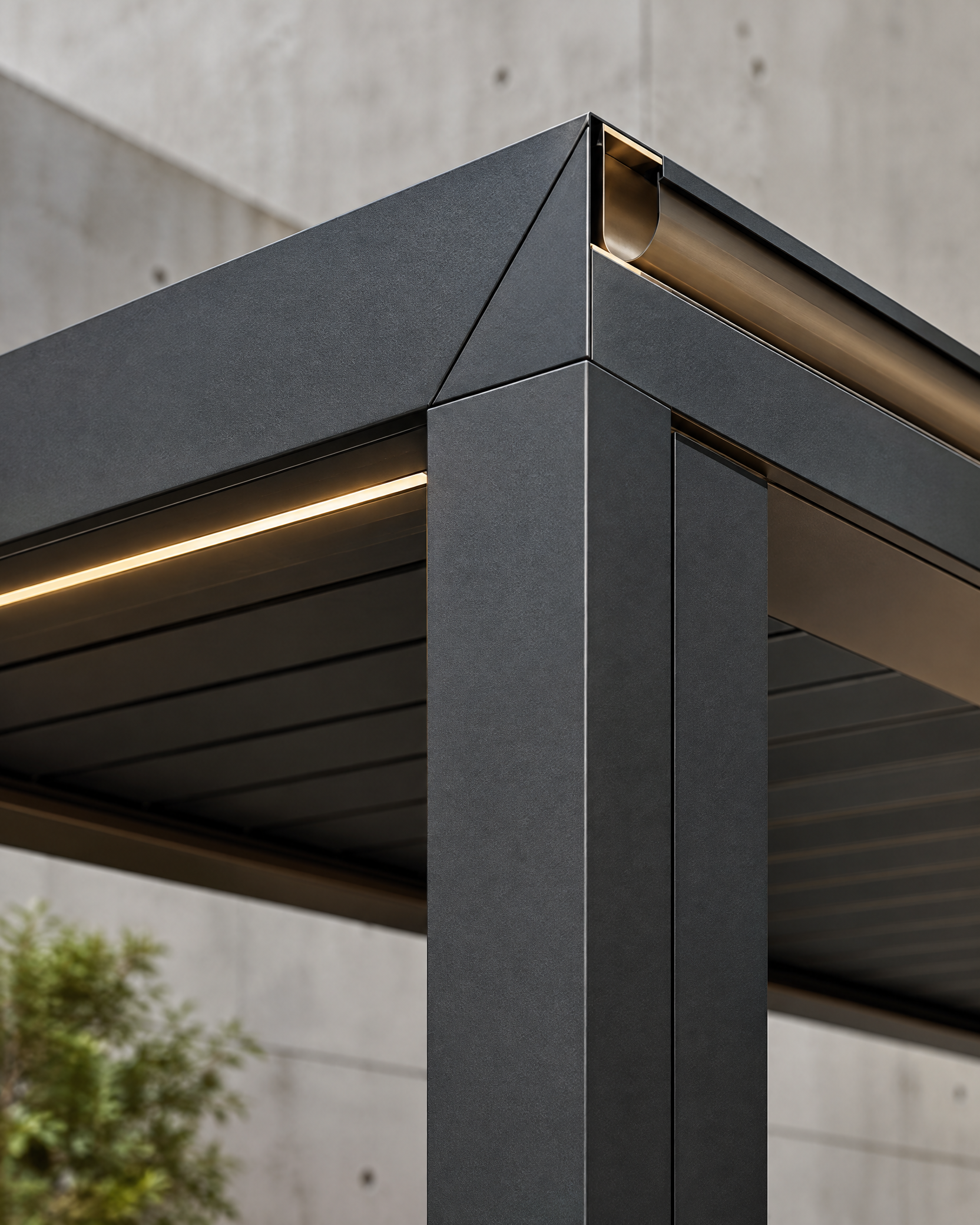
# What Foundations Does a Carport Need? A B2B Guide to Site Inputs, Bases and Installation Readiness
Carport foundation requirements are site-specific because a foundation is the civil and structural interface between the canopy, its support reactions and the ground. A commercial carport may use isolated reinforced-concrete footings or piers, linked foundations, a designed slab with local thickening, or another engineered solution. The appropriate option follows from a controlled survey, ground information, local frost and drainage conditions, structural reactions, connection geometry, permits and installation method—not from a generic footing sketch. Buyers should obtain a project-specific design from qualified local professionals, then use confirmed product data and approved embedment details to construct, survey and release the bases. The manufacturer’s role is to provide relevant system-interface information; the local design team and authority retain responsibility for site design and approval.
Buyer context and scope boundary
For a distributor, architect, contractor, developer, solar EPC or fleet buyer, foundation planning is an early procurement control. It determines which information must be requested from the manufacturer, which consultants must coordinate, and whether delivery and erection can proceed without reactive field changes.
This guide concerns permanent, freestanding commercial carports. It uses foundation to mean the engineered concrete support or slab interface, prepared ground, anchors or embedded items, and immediately related layout and drainage controls. It does not prescribe a footing depth, reinforcement schedule, bearing pressure, anchor type, wind or snow value, or suitability for a Carportiva system. Each depends on the project location, configuration, ground, code, approvals and erection plan.
Eurocode 7 applies to the geotechnical aspects of buildings and civil engineering works, with separate parts for general geotechnical rules and ground investigation and testing.[1] In North America, the locally adopted code and the responsible design professional similarly govern. Product information is an input to that work, not a replacement for it.
The useful buyer question is therefore: what verified site inputs, load-transfer design, dimensional controls and release evidence does this installation require? This avoids a frequent gap in which a frame is ordered before its foundation interface has been resolved.
Core principle: foundations transfer reactions, not catalog dimensions
A carport column does more than apply vertical weight to concrete. At each support, the engineered base must transfer the relevant design actions to the ground while controlling movement and delivering a durable, buildable connection. Depending on the system, actions can include compression, uplift, horizontal shear and overturning moment. Their governing combination can change with wind, snow, seismic criteria, roof drainage, photovoltaic equipment, canopy geometry and construction-stage loading.
The structural engineer translates support reactions and connection details into a foundation, reinforcement, anchorage and concrete-bearing design. The geotechnical professional evaluates relevant soil, rock, groundwater, settlement, lateral resistance and hazard conditions. The civil designer resolves finished levels, pavement, drainage and utilities. The surveyor establishes the location and elevation control. A base is reliable only when these interfaces agree.
Procurement rule: A preliminary layout is an information request, not permission to pour. Concrete work should be released only against a current, approved foundation package that identifies the carport configuration, drawing revision and coordinate system.
A generic detail may not reflect the final column grid, base plate, anchor group, pavement edge, electrical route, drainage fall or structural reaction. Nor is a traffic slab automatically a structural support for a carport column. A slab-based option can be suitable only when the engineer explicitly designs the local load path and connection.
This division of responsibility applies across Carportiva’s NordArch, NordFlat, SolarGrid and Titan systems. Spans, loads, coatings, foundations and compliance remain project-specific. Solar canopies also require electrical and water-management interfaces; fleet shelters may add circulation, impact-protection and pavement considerations.
Site inputs: survey, utilities and ground evidence
Establish one controlled horizontal and vertical reference
A useful survey identifies boundaries and easements, existing and proposed grades, drainage structures, pavement transitions, visible obstructions, access constraints and known services. It should also state the coordinate reference, units, benchmark or vertical datum, and the accepted design levels. NOAA describes national geodetic infrastructure as the framework for positioning activities, built around latitude, longitude and elevation.[2] At site scale, the comparable discipline is a single coordinate and elevation basis shared by civil, structural, survey and installation teams.
Request a field-ready coordinate schedule rather than relying on dimensions interpreted from a PDF. It should identify support centre lines, foundation centres, top-of-concrete elevations, grid or rotation information, datum and revision. For a sloping car park, confirm whether base elevations follow a plane, steps or individual levels. A visually level paving area is not a reliable installation datum.
Underground services require an equally early control. In the United States, the 811 service advises anyone who plans to dig to request marking of the approximate location of buried utilities before excavation and to wait for responses before breaking ground.[3] Equivalent local safe-excavation processes apply elsewhere. Records and markings are not an automatic design clearance; they must be assessed through the project’s required verification approach before locations, drainage and cable routes are fixed.
Scope ground information around the real design question
The geotechnical scope should reflect the proposed foundation concept, column grid, site history and risks rather than a fixed investigation quantity. FHWA describes subsurface characterization as important to planning, design, construction and operation, and emphasises investigation scoping, interpretation of field and laboratory data, hazard identification and reporting.[4] The same principle applies to a carport: the evidence should be sufficient for the decision being made.
Provide the geotechnical professional with a current concept layout, anticipated support locations and preliminary reactions when available. Identify known fill, former structures, soft or expansive soils, karst, retaining walls, slopes, contamination and groundwater. Ask what parameters, limitations, construction observations and response actions are needed for the intended foundation solution. If reactions are provisional, label them as such and set a confirmation gate.
A usable report relates the investigated locations to the layout and states the subsurface profile, groundwater observations, relevant design parameters within scope, limitations and required subgrade observations. It should say what happens if field conditions differ. That is more useful than a generic statement that a base is “suitable.”
| Site input | Why it changes carport foundation requirements | Buyer output before civil release |
|---|---|---|
| Controlled survey and utility review | Locates supports, levels, falls, conflicts and access constraints. | Coordinate schedule, datum, known-service status and ownership of unresolved conflicts. |
| Ground assessment | Informs bearing, settlement, excavation, groundwater and hazard decisions. | Site-related report, stated limitations and construction verification requirements. |
| Structural interface data | Defines actions and connection geometry the base must transfer. | Current configuration, reaction source, base detail and drawing revision. |
| Civil and drainage design | Controls water at bases, pavement interfaces and discharge routes. | Finished levels, drainage route, trench interfaces and required permits. |
| Authority pathway | Can govern setbacks, frost, flood, actions, excavation and approval. | Applicable criteria, review route and responsibility matrix. |
Treat frost, groundwater and drainage as design inputs
Frost protection cannot be reduced to one generic depth. It depends on the local climate, soil, moisture and selected system. NOAA explains that a frost-protected shallow foundation uses strategically placed insulation to raise frost depth around a building and that the air-freezing index helps estimate seasonal frost penetration; it also cautions that topography, nearby water and urban heat effects influence use of the data.[5] The local code and engineer must determine the project’s frost approach.
Water management should identify where roof runoff arrives, how surface water crosses the site, what occurs around bases, and where water is lawfully discharged. Coordinate gutters and downpipes with column locations, snow storage where relevant, trench routes and pavement falls. Seasonal groundwater can alter excavation and concrete-placement planning as well as long-term soil response.
Do not assume that a named granular layer provides drainage. FHWA notes that dense-graded base usually does not readily drain; when drainage performance is required, a more permeable open-graded layer and a connected subsurface drainage system may be needed.[6] That pavement guidance is a useful warning for carport buyers: material names do not establish hydraulic performance. The civil and geotechnical designers should specify the formation, grading, separation, compaction, drainage and protection required at the site.
Choose a base concept after the interfaces are known
Compare categories, not pre-approved details
Common concepts include individual reinforced-concrete footings or piers, linked or grade-beam arrangements, a structural slab with local engineered support, and specialty solutions selected for the ground and structure. These are categories, not standard answers. A solution that worked elsewhere may be unsuitable because support reactions, frost exposure, ground profile, finished levels or erection access differ.
Individual bases can simplify separation of supports but require coordinated excavation, level and runoff control. Linked bases affect reinforcement, trenching and pavement interfaces. A slab solution must explicitly address local bearing, punching, jointing, subgrade support and connection design. Specialty systems still require site, authority and connection verification.
The buyer need not select the structural answer. The buyer must ensure that the foundation designer receives final or clearly provisional reactions, base geometry, column grid, top-of-base elevations, adjustment range, drainage/pavement details and construction-stage assumptions. For cast-in items, request the approved embedment drawing early enough to test it against reinforcement and site geometry before concrete is scheduled.
| Base or interface condition | Decision criteria | Risk if it is missed |
|---|---|---|
| Isolated footing or pier | Soil response, frost strategy, uplift/moment, excavation, water route and elevation. | Variable levels, unsuitable formation or trapped water are discovered after layout is fixed. |
| Linked foundation or grade beam | Structural rationale, reinforcement continuity, drains, conduits and pavement joints. | Civil work conflicts with reinforcement or later utility routes. |
| Designed slab or thickening | Explicit load path, joints, local reinforcement, subgrade and base connection. | A parking slab is incorrectly assumed to carry concentrated column actions. |
| Cast-in anchors or embed plate | Coordinates, template, orientation, projection, congestion and tolerance. | The concrete is complete but the supplied structure cannot connect. |
| Post-installed anchorage | Approved design, concrete condition, drilling limits and installation controls. | Field drilling damages reinforcement or creates an unapproved anchor condition. |
| Electrical and drainage crossings | Conduits, bonding interface, downpipes, trenches and maintenance access. | Completed concrete is later cut or water management is obstructed. |
Maintain an unbroken load path
A reaction package is useful only when its conventions are clear. Confirm the point of application, axes, sign convention, applicable load basis, product configuration and revision. The local designer checks the complete path from roof framing to column, base plate, anchors or embedment, concrete, reinforcement, soil or rock, and any connected beam or slab. Do not combine information from different product revisions, support grids or action criteria.
Connection design is a separate coordination task. AISC identifies anchor rods, base plates and embedded plates as steel-to-concrete anchorage topics governed by structural specifications and material standards.[7] The base must address steel bearing, anchor forces, shear transfer, concrete response, reinforcement interaction, leveling or grout detail where designed, durability exposure and erection stability. When a shear lug or other defined shear-transfer feature is required, it must be detailed before construction rather than improvised after delivery.
For post-installed anchors, use only the engineered system and approved installation requirements. A buyer or installer should not substitute an anchor product, hole diameter, depth, adhesive or cure period to recover a programme without written design direction.
Maintain an interface register for each support type. It should list the support ID, drawing revision, reaction source, base/embedding detail, top-of-concrete level, anchor-template identifier, responsible party and acceptance record. This simple register prevents a civil or product revision from silently invalidating the base layout.
Control anchor geometry, concrete release and installation readiness
Make coordinate control measurable
Tolerances are not a general instruction to “be accurate.” They are limits, reference directions and measurement methods agreed between the connection detail, designer, fabricator, installation team and civil contractor. Their strictness depends on base-plate holes, connection adjustment and erection sequence. If a carport needs tighter requirements than usual practice, they must appear in the project documents before work starts.
Under AISC standard practice, anchor rods and embedded items are set to approved embedment drawings. Its default example limits vertical variation at the specified anchor-rod top to ±13 mm, with horizontal variation dependent on rod diameter; it also says that more restrictive conditions must be stated in the contract documents.[8] Those values are not a universal carport specification. They show why a buyer should demand an approved drawing and agreed tolerance instead of relying on a verbal template check.
Use a controlled setting-out sequence: establish the approved control points; verify footing positions and elevations; secure an identified rigid template or embed assembly against movement; then survey as-built anchor centres, group orientation, projection and top-of-concrete level against the approved schedule. AISC further calls for an as-built survey and design guidance where corrective action is necessary.[8]
Do not force a column onto a nonconforming group, enlarge holes, bend or heat rods, ream concrete, weld anchors or fit an offset plate merely to maintain programme. Quarantine the location, compare measured condition with the approved design, and obtain written direction from the responsible professional and manufacturer where relevant.
Release concrete against evidence, not a calendar date
“Cured” does not automatically mean ready for erection. Strength development depends on mix design, temperature, moisture and curing conditions. FHWA’s review of curing guidance notes that specifications may use prescribed curing periods but can also use field-cured cylinders, in-place methods or other accepted evidence connected to required strength.[9] The applicable release evidence and construction-stage load case should be defined in the project documents.
OSHA provides a useful U.S. steel-erection benchmark: before erection, written notification is required that footing, pier or wall concrete has reached either 75% of intended minimum compressive design strength, based on an appropriate ASTM field-cured-sample test method, or sufficient strength for erection loads. The same rule also addresses adequate access and a firm, graded, drained working area for delivery, storage and erection equipment.[10] Local rules and the project erection plan govern, but the principle is widely useful: confirm both concrete strength and physical site readiness.
A release record should identify foundation IDs, current drawing revision, placement information, required strength evidence, as-built acceptance where required, resolved deviations, access and drainage readiness. It should not make unsupported claims about safety, certification or approval.
Plan delivery inspection and erection as one operation
Hold a short readiness meeting before delivery with civil, structural, installation and logistics participants. Confirm access route, unloading equipment, laydown area, lifting method, traffic management, weather authority, protection of completed concrete and access for designed connection work. For solar carports, include the electrical contractor so that cables, bonding interfaces and drainage do not block structural erection.
On delivery, inspect the shipment against the packing list and visible condition before installation. Record apparent damage, packaging issues or discrepancies with photographs and item identifiers; segregate affected items and obtain written disposition. This is a delivery-condition check, not a claim that a product test, certification or site acceptance has occurred.
Before a lift, verify that released supports are accessible, dry enough for the approved work, correctly identified and free of new kerbs, trenches, stockpiles or barriers that obstruct the erection path. Stop and escalate if a base is flooded, damaged, misaligned or inconsistent with current drawings.
Six-step buyer workflow
| Step | Buyer action | Gate output |
|---|---|---|
| 1. Define project basis | Issue location, concept layout, intended use, product family, authority route and programme. | A responsibility matrix and clearly labelled preliminary package. |
| 2. Build site evidence | Assemble survey, utility, ground, drainage and access information. | Controlled datum, site evidence and visible unresolved-risk register. |
| 3. Freeze interfaces | Obtain relevant product data; have local professionals design foundations and approvals. | Approved project-specific foundation, connection and drainage documents. |
| 4. Set out and construct | Locate utilities as required; prepare formation; install reinforcement and embeds; place concrete. | Traceable pre-pour and placement records; deviations escalated. |
| 5. Verify and release | Survey as-built geometry, obtain required strength evidence and confirm safe access. | Written release for the defined erection stage. |
| 6. Deliver and install | Check delivered items, manage laydown/lifting and retain change control. | Coordinated installation and handover records. |
Mid-article CTA: For a commercial carport procurement package, submit an inquiry with the concept layout, location, intended product family and available survey or design information. Carportiva can identify relevant system-interface inputs; local professionals should determine the foundation design. You may also email info@carportiva.com.
FAQ and conclusion
Does every carport need concrete footings?
No single answer is reliable. Permanent freestanding carports often use reinforced-concrete supports, but the form may be isolated bases, a linked system, a designed slab interface or another engineered solution. The local professional must consider reactions, ground, water, frost, code, geometry and installation method.
Can an existing parking slab support a carport?
Possibly, but it should not be assumed. The engineer must evaluate local column actions, slab thickness and reinforcement if known, joints, support condition, edges, anchorage, drainage and any strengthening need. A slab that carries vehicles may not be designed for concentrated column actions.
How deep should a carport foundation be in a cold climate?
There is no universal depth. Local frost design depends on climate, soil, moisture, code and the adopted structural system. NOAA’s frost-protected shallow-foundation guidance illustrates that an engineered insulation strategy can be part of the answer, but the local design team must establish the applicable detail.[5]
Who sets the anchor rods or embedded plates?
Project documents must assign responsibility. AISC’s standard-practice framework assigns setting and as-built verification to the construction representative in accordance with approved embedment drawings, with design guidance for corrective action.[8] A carport project should state its own responsible parties, template, tolerance, records and escalation path before the pour.
When can installation begin?
Only after the project’s defined release conditions are met: required concrete-strength evidence for erection-stage loads, accepted base geometry, resolved nonconformances, safe access and laydown, and an approved erection method. OSHA’s U.S. steel-erection rule demonstrates the importance of both concrete readiness and a firm, drained work area.[10]
Do product drawings replace a local foundation design?
No. Product drawings and reaction data are essential inputs, but they do not replace site-specific geotechnical, civil and structural design or authority approval. They must be coordinated with the final survey, local actions, drainage, connection and erection plan.
The correct answer to “What foundations does a carport need?” is a controlled process rather than a generic base: collect site evidence, translate current reactions into a local engineered load path, set anchors from approved coordinates, verify the work and release the site for the planned installation stage. Review the related aluminium carport snow-load guide when climate actions are being scoped. To request relevant product-interface information, use [the inquiry form](/inquiry) or email [info@carportiva.com](mailto:info@carportiva.com).
References
Bring the actual project brief to the engineering table.
Share your location, layout, target application and available technical inputs. Carportiva can help identify the relevant product-interface information before a project-specific commercial discussion.
Request a project discussion